Main Menu
- Home
- Product Finder
- Calibration Systems
- Calibration Services
- Digital Sensing
- Industrial Vibration Calibration
- Modal and Vibration Testing
- Non-Destructive Testing
- Sound & Vibration Rental Program
- Learn
- About Us
- Contact Us
The LaserTach LT2 is a unique offering that combines a common measurement (rotational speed) with a standardized measurement interface (ICP®1 sensors). Dynamic signal analyzers have long leveraged the fact that they could measure dynamic phenomena
such as force, pressure, acceleration, and strain with a 2-wire constant current excitation type sensors (a.k.a. ICP or IEPE sensors).
This standardization allows simplified cabling and a lower cost measurement channel. The traditional tachometer
measurement contrasts this situation by requiring a (non-standardized) array of power supply requirements and multi-wire cabling.
Yes, the LaserTach LT2 uses the latest in LASER technology to operate down to the 2 mA minimum of the ICP standard.
The LaserTach LT2 is a Class 2 device. While considered safe, users should avoid looking into the device. The strength of the beam is similar to that of a handheld laser pointer.
No, the LASER operates continuously. The upper RPM limit is a consequence of needing to periodically sample the ambient light conditions to adapt to changes in lighting levels.
The Modal Shop recognizes the need of our customers to reference the spectral content of dynamic measurements to shaft speed. By offering the LaserTach, TMS has opened the concept of simplified cabling to those ICP sensor users that need a tachometer signal. In addition to that, acquiring rotational speed data on a sampled FFT data channel offers several advantages:
No. The output voltage of the LaserTach LT2 drops a minimum of 0.3 Vpp upon detection (See Question 8) of reflected 680 nm light that surpasses the detection threshold. The level returns to bias voltage otherwise. The amplitude of the bias and voltage drop will vary based on the ICP constant current supply.
The output voltage level of the LaserTach LT2 generally drops more with increased constant current supply. Figures 1a and 1b show the typical output levels with a 5 ft (1.52 m) length of coaxial cable. The AC response is typically of most interest because it represents the amplitude change for a rotating shaft into an AC coupled data acquisition channel. The DC Bias Point response is what would be measured with a volt meter or DC coupled input.
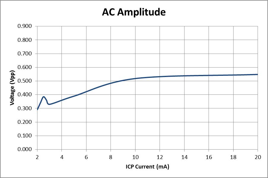
Figure 1a - LaserTach Output Voltage Drop with Change in ICP Current
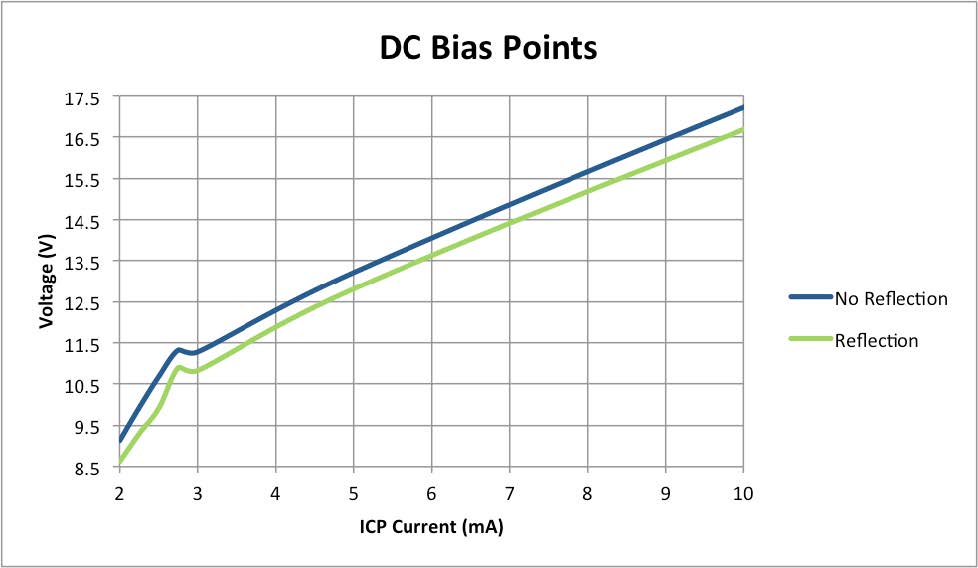
Figure 1b - LaserTach Output Voltage Drop with Change in ICP Current
The amplitude of this voltage drop will vary based on the ICP constant current supply to the LaserTach LT2 (See Question 7). Figure 2 shows a time history of LaserTach output voltage. In this case, the reflective surface was a small (<10%) portion of the overall shaft circumference. The pulse train looks like a series of blips. This is a 265 RPM wave form with an AC coupled data acquisition system. The capactive charge and discharge portions of the waveform is coming primarily from the data acquistion AC coupling.
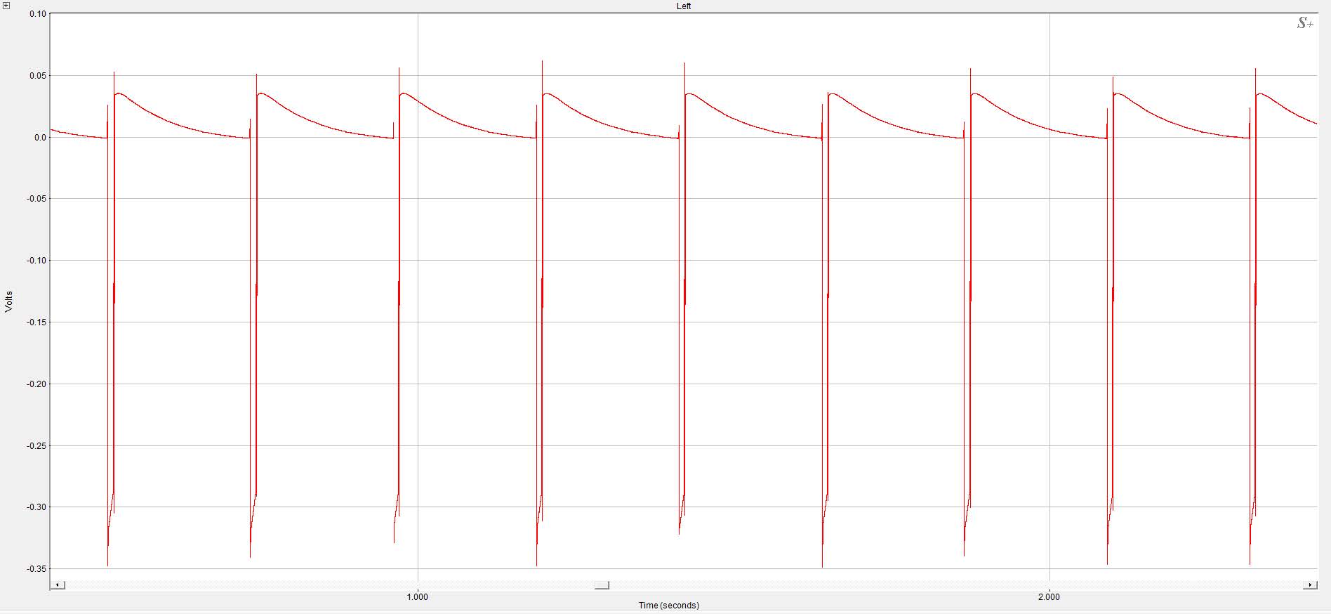
Figure 2 – LaserTach Pulse Train With Small Reflective Surface Coverage and 265 RPM
Figure 3 shows a LaserTach LT2 pulse train when targeted at a shaft with over 30% reflective surface coverage and 30,000 RPM. This waveform begins to approximate a square wave. Both Figure 2 and Figure 3 show rippling of the output at the voltage transition points, which is typical ‘ringing’ of anti-alias filters when the data is acquired on a sampled FFT analyzer channel.
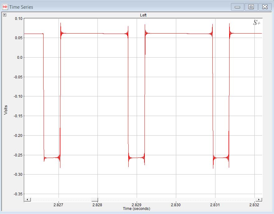
Figure 3 - LaserTach Pulse Train With High Reflective Surface Coverage and 30,000 RPM
The LaserTach LT2 detects the change in reflected light of 680 nm wavelength. The LaserTach LT2 incorporates an optical bandpass filter lens cap so it is generally immune to the affects of ambient light and sunlight.
The LaserTach LT2 incorporates an optical band pass filter and it is generaly not sensitive to infrared heat sources.
The LaserTach LT2 is not designed for use in environments above atmospheric pressure. Subjecting the LaserTach LT2 to significant differential pressures by threading it into the wall of a pressurized vessel will result in catastrophic failure of the device and possibly explosive disassembly.
Yes, although any opacity in the glass will reduce the operating range.
Rain usually doesn’t affect the performance of the LaserTach LT2 unless the relative humidity causes moisture to condense in the optics. The LaserTach LT2 is an optical sensor, so visibility through the sensing medium directly affects the performance.
The LaserTach LT2 is an optical sensor that detects changes in the intensity of reflected light of 680 nm wavelength. The transparency of any liquid through which the LaserTach is detecting this reflected light will affect the performance.
Pure water
will work better than water with contaminants. Any wave field that exists in the water will certainly distort the light detected on the optic sensor, and could reduce performance, or make measurements impossible. Any refraction of the reflected
light will also reduce the capabilities of the LaserTach LT2 (This will be most noticeable when holding the LaserTach at an angle away from the normal to the water’s surface).
Warning: The LaserTach LT2 is not designed to be submersed in any liquid. Pointing the LaserTach through a glass or clear plastic porthole or sightglass is a good way to measure through liquid media.
The LaserTach LT2 operates using the limited power budget offered to ICP circuits. For this reason, the LaserTach LT2 requires retroreflective tape for best results. The use of contrasting colored surfaces dramatically reduces the operating range of the LaserTach. In a test case, the LaserTach LT2 detected a target created on a laser printer from a maximum of 3-1/2 in (8.9 cm). The target was printed on color copy paper with a brilliance rating of 96.
Reflective surfaces are designed to reflect light away from the surface at an angle equal to the angle at which it hits the surface. Reaching back to our freshman physics book reveals that classic relationship ‘the angle of incidence equals
the angle of reflection’, which is plotted in Figure 4. A reflective surface will reflect light directly back to the source only when the source is 90°, or normal, to the surface.
Figure 5 illustrates the behavior of a retro reflective
surface, reflecting light directly back to the source, regardless of the angle of incidence.
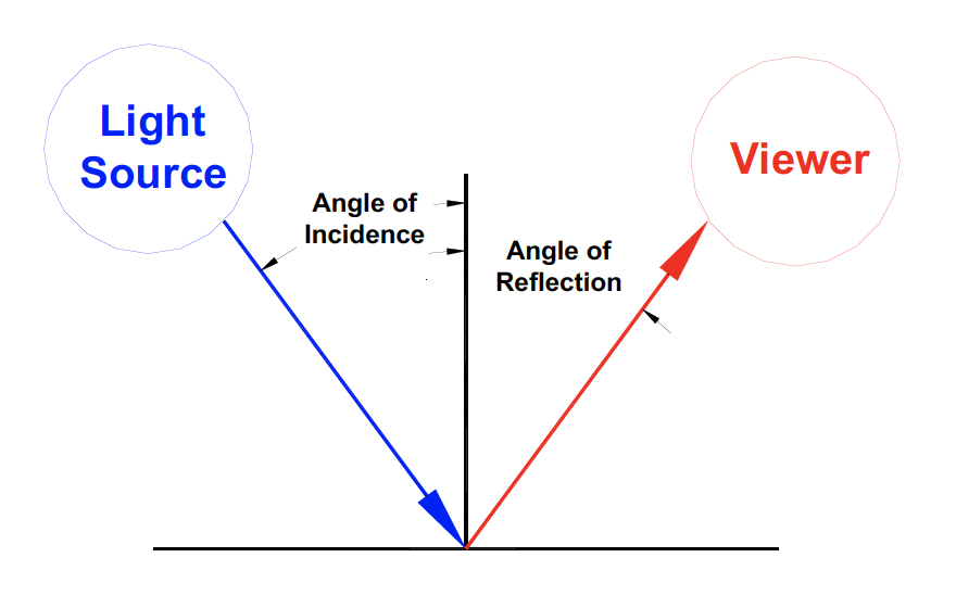
Figure 4 – Reflection: Angle of incidence equals angle of reflection
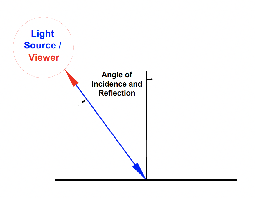
Figure 5 - Retro reflection: The performance of the LaserTach LT2 is greatly enhanced when using retro reflective tape
3M Corporation markets retroreflective materials under its ScotchliteTM brand. The Modal Shop also offers Model LT-Tape, which is retroreflective.
The LaserTach has operating temperature range of 14°F to 122°F (-10°C to 50°C). The temperature range for storage is -40°F to 185°F (-40°C to 85°C).
This is a limitation that can be traced back to the limited power budget of ICP constant current powered devices at the minimum 2mA level. The LaserTach LT2 needs to periodically sample the ambient light conditions to dynamically adjust the reflected light comparison threshold.
The LaserTach LT2 is a DC coupled device. The LaserTach LT2 is capable of detecting 0 Hz, steady state changes in reflected light. However, since it is by definition attached to an ICP sensor signal conditioner, the signal will most likely be AC coupled
by the signal conditioner circuitry. This makes the low frequency limit of the LaserTach equal to the low frequency cutoff of the signal conditioner AC coupling circuitry.
There do exist DC coupled ICP signal conditioners but they are not
common. Certain DC voltage tachometer channels may support the LT2 voltage levels.
It depends. We don’t recommend positioning the LaserTach closer than 2 in (5 cm) from the target to detect the reflected laser light.
The maximum distance varies based on the ICP current level and lighting conditions. Each LaserTach LT2 is tested to ensure at least 20” (51cm) at 2mA. Under some conditions, the range can be farther. Increasing ICP current to 3.5mA or greater
will maximize the range.
This is with the LaserTach LT2 positioned on the normal to the mounting surface of a retro reflective target. Introducing an angle to the mounting surface reduces the operating range. Typical data is shown in Figure
6.
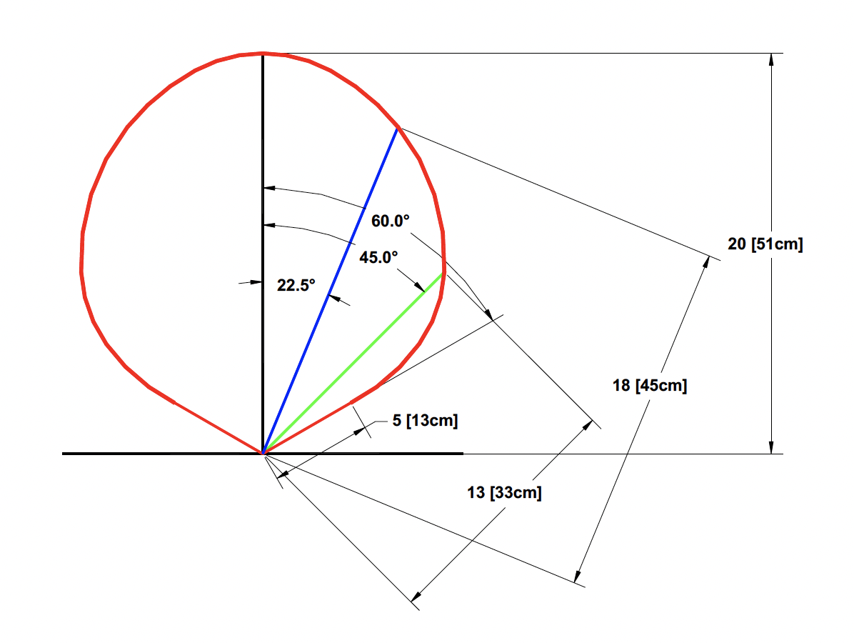
Figure 6 – Typical Operating Envelope For LaserTach
This is a limitation of the energy supplied to the Class 2 laser from the ICP sensor signal conditioner.
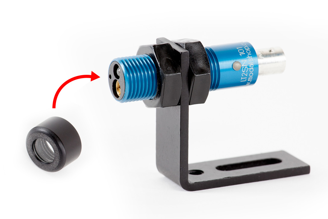
No. Do not adjust the slotted cap of the laser. The units are focused during acceptance test at the manufacturer. Adjusting this piece may reduce performance of the LaserTach or damage the laser itself, and voids warranty.
We have successfully tested operated the LaserTach LT2 at angles of incidence of up to 60° when using retro reflective tape.
Although torsional vibration analysis is not the primary application for the LaserTach LT2, it has been successfully used in some circumstances. The utility of the LaserTach LT2 for torsional measurements is still being evaluated. It will depend on
the maximum rotation rate of interest and the number of pulses per rotation below the maximum RPM of the LaserTach LT2.
While the LaserTach LT2 is low jitter, most ICP inputs on DAQ systems are sampled at a fixed rate and that rate of sampling
has an inverse relationship to RPM measurement accuracy.
Figure 7 shows an RPM measurement jitter analysis for a 25,600 samples / second (10kHz Fmax) data acquisition system. The jitter is lower for higher sample rates and higher for lower
sample rates.
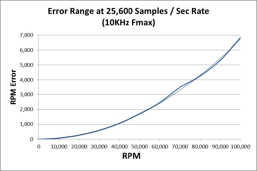
Figure 7 : DAQ RPM Measurement Error
Yes, although you should be aware that that the frequency content of the signal will depend upon the accurate spacing of the stripes. Also keep in mind that maximum RPM effectively becomes the number of stripes times the shaft RPM.
Between 1% and 10% of the shaft circumferance is usually optimum. The LaserTach LT2 continuously scans so it can detect reflections smaller than is phyiscally practical to place on the shaft.
A limiting factor is the sample rate of the DAQ system interfaced to the LaserTach LT2. The reflective region must be wide enough to consistently be sampled each rotation. The following equation will provide the minimum percentage that needs
covered for a given RPM, Sample Rate, and number of samples. % Covered = (Number_of_Samples * RPM) / (60 * Sample_Rate) Where, Number_Of_Samples is the number of samples to capture to ensure accurate triggering and pulse detection. 10 is a good
rule of thumb.
RPM is the maximum shaft rotation rate to measure Sample_Rate is the number of samples per second. This is the actual sample rate and not the Fmax or measurement bandwidth.
For example, a 10,000RPM rotation with a sample
rate of 25,600 (often an Fmax of 10,000 Hz) and 10 samples.
(10 Samples * 10, 000 RPM) / (60 cycles * 25,600 Samples) = 6.5%