Main Menu
- Home
- Product Finder
- Calibration Systems
- Calibration Services
- Digital Sensing
- Industrial Vibration Calibration
- Modal and Vibration Testing
- Non-Destructive Testing
- Sound & Vibration Rental Program
- Learn
- About Us
- Contact Us
 Acoustic transmission may be the most important communication
method in the world. To enable this communication, we enjoy a vast diversity of microphone designs that are used in telecommunications, professional audio, and security. Of course, if you are reading this article, you are most likely interested in
Test & Measurement applications, where we actually measure sound, rather than simply transmitting it. All Test & Measurement applications share three common traits.
Acoustic transmission may be the most important communication
method in the world. To enable this communication, we enjoy a vast diversity of microphone designs that are used in telecommunications, professional audio, and security. Of course, if you are reading this article, you are most likely interested in
Test & Measurement applications, where we actually measure sound, rather than simply transmitting it. All Test & Measurement applications share three common traits.
Ultimately, these three things require the calibration of the microphones and related instrumentation to ensure data quality.
The global calibration and metrology infrastructure for instrumentation allows the Test & Measurement community to effectively compare results across organizations, industries, and even continents. There are two major components of this infrastructure that enable these comparisons: traceability and internationally accepted calibration techniques.
Traceability is an unbroken chain of measurements that can be traced back to what we call a primary method of calibration that is performed with an intrinsically stable and repeatable experiment.
The internationally accepted calibration technique specific to acoustics is found in the IEC 61094 series of standards for condenser microphones and the calibration of these microphones. While IEC 61094 defines calibration techniques for condenser microphones, we also use parts of it to calibrate array microphones, such as PCB Model 130 Series.
A common technique is the IEC 61094-6 electrostatic actuator method, combined with the insert voltage technique. This has three main limitations:
So for array microphones, the IEC 61094-5 comparison method is often used for calibration. This method can also be used on condenser microphones. Calibrators are now available to integrate into existing, proven calibration systems. These systems, such as the one shown below, offer control and automation of the calibration process. Other standalone, portable calibration systems are also available.
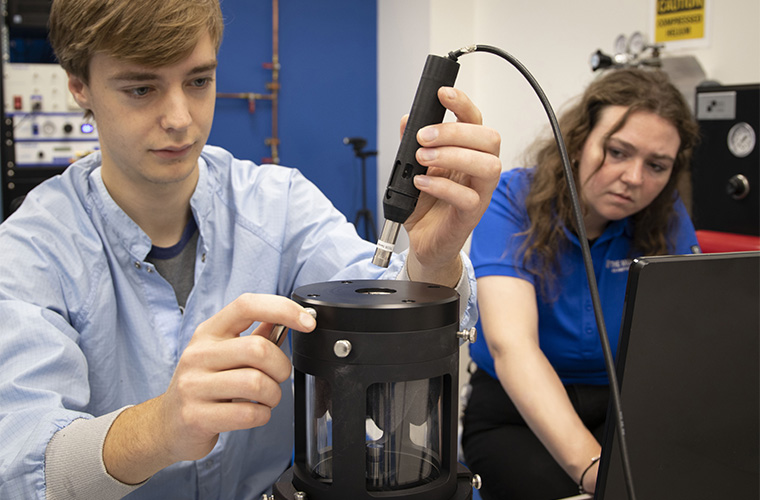
Figure 1 - A microphone being calibrated per IEC 61094-5 with a Microphone Comparison Calibrator.
In this technique, the microphone under test and a reference microphone are used. The reference microphone needs to have been recently calibrated precisely at a high level in the chain of traceability. The two microphones are placed face-to-face using relatively simple calibration equipment and exposed to a sound field simultaneously. A simple comparison is made between the voltage output of the microphone under test and the reference microphone. According to IEC 61094-5, Annex D:
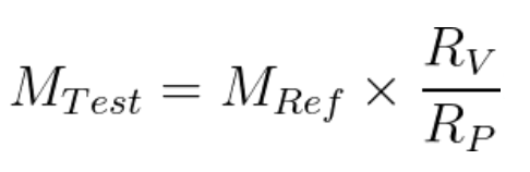
Where:
Since MRef is known, we simply measure the voltage output of both microphones to calculate MTest, and this measurement is performed at multiple frequencies, with either sinusoidal or broadband excitation.
There are three response types for precision condenser microphones:
These response types describe the sound field in which the microphone is designed to operate. Both the microphone design and the test configuration affect the sensitivity of the microphone at higher frequencies. This effect is characterized by the microphone manufacturer and published as a correction curve. More details on field types are available in the PCB Microphone Handbook.
For the purpose of calibration, we must understand that the IEC 61094-5 method specifies a pressure response measurement. For this reason, we recommend using a pressure response microphone as the reference microphone. To calibrate a free field or random incidence microphone, the appropriate correction curve should be applied to the results from the pressure field calibration. This ‘corrects’ the pressure field measurement (the pressure response) to a free field or random incidence response. Expanding on the sensitivity equation shown above:
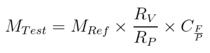
Where:
Regular microphone calibration is important for repeatability in testing. As a team of Test & Measurement experts, we understand the importance of having a calibration solution that provides precise results, reliable hardware, and is inherently user-friendly. Options for microphone calibration methods outlined in IEC 61094 vary widely in cost and practicality. Regardless of the calibration method chosen, the chain of traceability should be considered. The IEC 61094-5 comparison method with correction curve applied when necessary is a cost-effective and straightforward method for calibrating array and condenser microphones.