Main Menu
- Home
- Product Finder
- Calibration Systems
- Calibration Services
- Digital Sensing
- Industrial Vibration Calibration
- Modal and Vibration Testing
- Non-Destructive Testing
- Sound & Vibration Rental Program
- Learn
- About Us
- Contact Us
When an object vibrates in the presence of air, the air molecules at the surface will begin to vibrate, which in turn vibrates the adjacent molecules next to them. This vibration will travel through the air as oscillating pressure at frequencies and amplitudes determined by the original sound source. The human ear transforms these pressure oscillations, or sound, into electrical signals that are interpreted by our brains as music, speech, noise, etc. Microphones are designed, like the human ear, to transform pressure oscillations into electrical signals. These signals can be recorded and analyzed to tell us information about the original source of vibration or the nature of the path the sound took from the source to the microphone. This is exhibited in testing of noise reducing materials. Sound pressure must be analyzed in the design stages to not only protect the materials around it, but also to protect the mechanism designed to perceive it, the human ear. Like the human ear, microphones are designed to measure a very large range of amplitudes typically measured in decibels (dB), and wide ranges of frequencies measured in hertz (Hz).
Microphones measure sound pressure. There are a few different designs for microphones. The most common designs for test and measurement applications are modern Prepolarized Condenser Microphones, Externally Polarized Condenser Microphones, and Piezoelectric Microphones, commonly referred to as Acoustic Pressure Sensors. Other microphone designs include Carbon Microphones, Dynamic, Magnetic Microphones, Fiber Optic Microphones, Laser, Ribbon and Micro Electro-Mechanical Systems (MEMS).
Condenser microphones operate on a capacitive design, shown in figure 1 and utilizes basic transduction (the conveyance of energy from a donor to a receptor) principles and will transform the sound pressure to capacitance variations, which are then converted to an electrical voltage. This is accomplished by taking a small thin diaphragm and stretching it a very small distance away from a stationary metal plate, called a “backplate.” In the presence of oscillating pressure, the diaphragm will move which changes the gap and thus the capacitance between the diaphragm and the backplate. In order to measure the changing capacitance of the microphone due to the sound field, a voltage is applied to the backplate to form the transducer. Changes in the acoustic pressure will deflect the diaphragm and produce a voltage from the capacitor proportional to the original pressure oscillation corresponding to the individual microphone’s sensitivity.
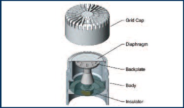
Figure 1: Condenser Microphone Components
In order to convert a change in capacitance to a change in voltage, the charge applied to the backplate can be generated by two different methods. The first is an externally polarized microphone design where an external power supply is used. The voltage source on this traditional design is 200 volts. The second, newer design is called a prepolarized microphone design. This modern design utilizes an electret layer placed on the backplate. An electret is a material in which a constant electric charge is placed. This charged material is what supplies the voltage for polarization.
This design, when coupled with an Integrated Circuit Piezoelectric (ICP®) preamplifier can provide great advantages. An inexpensive constant current supply can power the unit, instead of the more expensive externally polarized power supplies. Standard coaxial cables with BNC or 10-32 connectors can be used, instead of LEMO® 7-pin connectors and cables. The coaxial cables can be driven long distances without degradation of the signal. PCB® is the founder of ICP® (Integrated Circuit Piezoelectric) technology, which all the modern prepolarized acoustic designs are based upon. The modern prepolarized designs are becoming increasingly popular for laboratory test and measurement, and field applications, due to low cost, ease of use, and interchangeability with IEPE (the generic trade name for ICP®) compliant accelerometers.
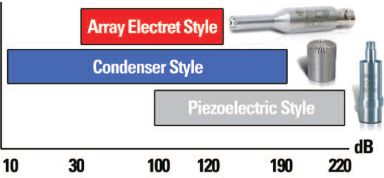
Array microphones are an electret style. Although the dynamic range and frequency range are not as wide as the IEC 61094 compliant condenser microphones, as shown in figure 2, it’s value oriented design makes it an excellent choice for large channel measurement test and measurement applications concerned with the human audible range. See pages 13 & 17 for additional information and applications.
Piezoelectric microphones use a quartz or manmade ceramic crystal structure, which is similar to electrets in that they exhibit a permanent polarization and can be coupled with an ICP® design. Although these acoustic sensors have very low sensitivity levels, they are very durable and are able to measure very high amplitude (decibels) pressure ranges. Conversely, the noise floor level on this type of microphone is generally very high. This design is suitable for shock and blast pressure measurement applications.
Carbon microphone designs are becoming less popular, but are a low-cost type. This design is a very low quality acoustic transducer type. An enclosure is built. This enclosure houses lightly packed carbon granules. At opposite ends of the enclosure, electrical contacts are placed, which have a measured resistance. When the pressure from an acoustical signal is exerted on the microphone, it forces the granules closer together, which decreases the resistance. This change in resistance is measured and output. A typical use of this item can be seen in early basic designs of a telephone handset.
Magnetic microphones are a dynamic microphone. The moving coil design is based on the principal of magnetic induction. This design can be simply achieved by attaching a coil of wire to a light diaphragm.
Upon seeing the acoustical pressure, the coil will move. When the wire is subjected to the magnetic field, the movement of the coil in the magnetic field creates a voltage, which is proportional to the pressure exerted on it.
Microelectromechanical systems (MEMS) microphones consist of etched silicon and are becoming increasingly popular due to their low cost. But their specifications for frequency, amplitude, sensitivity and stability, limit their use for test and measurement applications, for now. Future developments may enable this to be a viable design for use in test and measurement applications.
The most popular test and measurement microphones are the capacitor condenser designs. The focus of the following technical guide will be based on these Prepolarized and Externally Polarized condenser designs.
Microphones measure broadband sound pressure levels from a variety of sources. When the microphone signal is post processed, the frequencies can be correlated with the sound source, and if necessary, related back to the wavelength of the sound. Acoustical measurement of this sound, through the use of high precision condenser microphones, provides a better understanding of the nature of the sound. In some applications there are a number of microphones that can work and measure the sound pressure level. Common diameters for condenser microphones are 1/4” (6mm), 1/2" (12 mm), 1” (25mm). The key is to determine which microphone will offer the best solution for a required application.
Click to go to PCB website to download full microphone handbook.