Main Menu
- Home
- Product Finder
- Calibration Systems
- Calibration Services
- Digital Sensing
- Industrial Vibration Calibration
- Modal and Vibration Testing
- Non-Destructive Testing
- Sound & Vibration Rental Program
- Learn
- About Us
- Contact Us
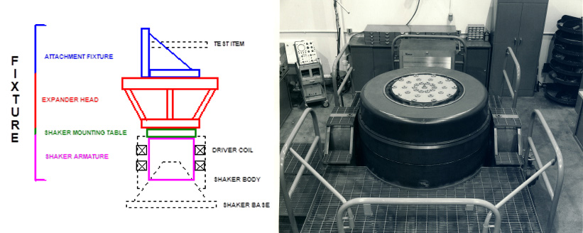
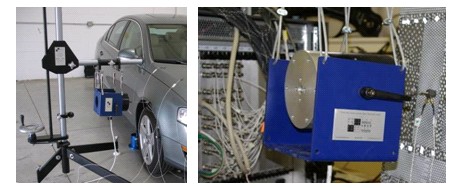
With conventional vibration testing using a shaker with a traditional mounting platform design, the test article is directly attached to the top surface of the armature with some base excitation applied, usually monitored by controlling prescribed acceleration. The device under test (DUT) is normally subjected to an operating environment, generic spectrum or an excessive environment to determine if the equipment is suitable for the intended service. A typical configuration is shown.
In the early days of modal testing with shaker excitation, smaller shakers were used to apply low level excitation to be able to measure a frequency response function. Usually the shaker was attached with a long rod, commonly referred to as a stinger or quill, in order to impart force to the structure. (The purpose of the stinger was to try to dynamically decouple the shaker from the structure.)
Because these traditional shakers were typically used for base excitation, the armature attachment configuration was not optimal. Usually, some type of left-right thread arrangement was made or a collar was designed to enable an easier attachment to the shaker. It was a rather difficult arrangement no matter how the connection was made. In addition, thought had to be given to shaker position and actual length of the stinger needed. If a different length stinger was needed, then the shaker needed to be reoriented and realigned as different stinger lengths were used for the modal test. Overall, the set up of the shaker for a modal test was very difficult and cumbersome.
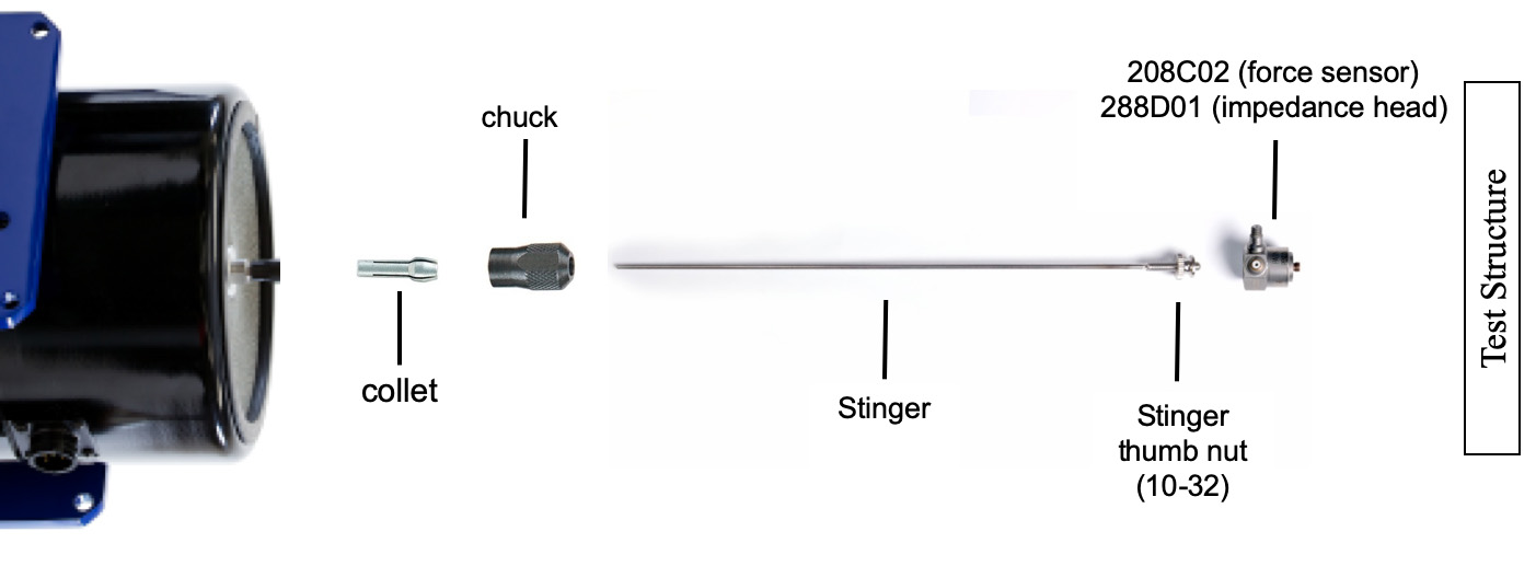
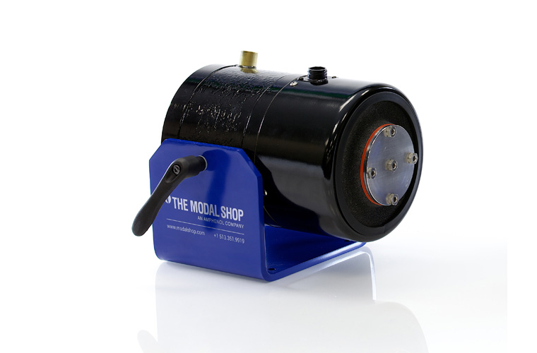
Due to all these problems, thought was given to specific design configurations that were better suited for modal testing applications. This gave rise to the through-hole armature with a chuck and collet design (like gripping a drill bit on a hand drill) that enabled very easy attachment of the shaker to the modal test article. A long stinger can be slid into the shakers through-hole armature, threaded to the force transducer attached to the test article, properly aligned, and then clamped down with the chuck and collet at the appropriate length. These components are shown as an exploded view below and a video demonstrating actual installment is posted at http://www.youtube.com/watch?v=VP_X-8TUtOU. This design also accommodates stingers of different lengths if needed. This arrangement is so simple that it is difficult to imagine having to set up the test without this important feature.
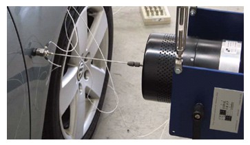
Many times it is difficult to support a shaker from a floor-mounted fixture, such as the Model 2050A lateral excitation stand shown below. In these cases, the shakers may be hung from a support cable attached above the test article. Often masses are attached to the base of the shaker trunnion to provide more inertia to push against for improved performance, typically this only an issue at very low frequency in the sub-10 Hz range.
The alignment of the shaker is very important. Significant misalignment may cause damage and/or unnecessary wear to the shaker armature due to resulting side loads. In addition, the forces imparted to the structure will be measured incorrectly due to transverse load components, and the measured response functions will not be correct. This alignment issue causes difficulty in any shaker test. Care must be taken to provide the best alignment possible to attain the best possible measurements.
(In a future updates of this FAQ, measured frequency response functions will be included to show the distortion that may commonly result due to poor alignment.)
In setting up a shaker test, typically the stinger is slid into the shakers through-hole armature with the force transducer or impedance head attached to the end of the stinger. With the shaker collet loosened, the stinger can be extended in and out of the armature to obtain the desired length. Once this is done then the force gage or impedance head mounting pad can be affixed to the structure; the mounting pad is often attached using dental cement, two-part quick epoxy or a Loctite adhesive. Often a piece of foil adhesive tape is first adhered to protect the surface of the test article, with the mounting pad bonded to the tape.
If the alignment is correct, the shaker stinger will easily unthread from the force transducer or impedance head AND also thread right back in without any binding or difficulty whatsoever. This should be accomplished without the stinger putting side load onto the shaker armature, sliding easily within the chuck and collet assembly, which assures that the shaker and stinger are properly aligned.
At times there may be a threaded mating hole in the structure for mounting the force gage or impedance head and attaching the shaker. Alignment in these situations is much more difficult, requiring that the shaker and/or the test article be moved such that the fixed threaded hole places the stinger exactly in the correct position. The main point is that the shaker must be aligned such that the stinger can be very easily threaded in to the force gage or impedance head with no difficulty or binding whatsoever. For more details check the Modal Shaker Setup Tutorial video
Shakers actually only have one maximum force rating. However, shaker systems (i.e. the electrodynamic exciter paired with a specific power amplifier with accessories like a cooling package) have different system ratings. For example, the 2100E11 modal shaker has a maximum force rating of 100 lb pk. To attain this maximum force rating, the shaker must be driven by an amplifier with adequate power, for example, the 2100E18 power amplifier, which is rated at 1000 W. Additionally, to attain this maximum force rating without damaging the shaker, forced air cooling must be supplied to the shaker to dissipate the heat generated from the current flowing through the coils using, for example, the 2050E03 cooling package.
For typical modal applications, lower input force levels are desired. Therefore, the 2060E shaker can be used with instrumentation amplifiers such as the 2100E21-400 and 2050E05 power amplifiers. Some of the system solutions include certain features of interest to modal test engineers, such as voltage and current monitoring of the amplifier output, safe start, and a safety interlocks. Given the 400 W nominal power rating of these power amplifiers, the maximum attainable output force level of the system is only specified at 30 lbf pk.
When performing experimental modal analysis with shakers, generally all the accelerometers are mounted and cables are run from the structure to the data acquisition system before the shakers are attached to the test article. The shaker set up, stinger attachment, and alignment are usually the last steps in the process. If attached before the rest of the instrumentation is set up on the structure, the shaker could be damaged due to settling of the structure on its soft supports or shifting of the structure during the course of test setup. This will cause misalignment of the shaker/stinger setup which may lead to incorrect measurements. As a result, the shaker is generally the last item to be set up and aligned when performing modal testing.
Whenever a modal test is performed using shaker excitation, the shakers should be disconnected from the structure while data is not being acquired, whether it is between different test configurations or during periods of inactivity, for example over a lunch break or overnight. There are many reasons for this. During the set up of the test, there may be some shifting or settling of the test article. Commonly, airbag soft support systems are used to provide a free-free boundary condition during testing. These may lose air over time, shifting the structure. Additionally, an elastic shock cord (bungee) will creep in length over a period of time. In between tests, there may be some reconfiguration of the test article for multiple sets of test data. For instance, a vehicles gas tank may be empty in one test and then filled in another test. Because of this, there may be a general shifting or redistribution of mass in the system, which in turn causes shifting of the test article relative to the original alignment of the shakers to the structure.
If the shakers are attached during down time between tests while the structure undergoes necessary reconfigurations, there may be side loads applied to the stinger attaching the shaker to the structure and the alignment of the system may be disturbed. These side loads will potentially bend the stingers, or worse, cause damage to the shaker armature. In addition, it may become difficult to disassemble the stinger from the structure once the alignment has been disturbed.
If the shakers are disconnected during periods between test cycles, it will be obvious if any misalignment has occurred upon reattaching the shakers for the next set of tests. If the original shaker alignment is disturbed, then the shaker must be realigned in order to provide a proper attachment to the system.
The trunnion is a very important component of the shaker system. It is the U shaped support base that supports the electrodynamic shaker body itself. The shaker trunnion allows the shaker to be rotated in place and provides convenient mounting holes for hanging from a lateral excitation stand, for example the 2050A shaker stand. Without a trunnion, it is very difficult to set up a shaker for modal testing. The trunnion allows the shaker to be configured in different skewed orientations and angles for excitation. Skewing the input force can be particularly important for exciting structures with vertical and lateral modes that are highly uncoupled. The trunnion is also beneficial when aligning the shaker to the structure for modal testing.
When setting up for shaker testing, the shaker must be aligned with the structure in order to excite the structure in the desired direction. Most times the shaker force levels used are very low in amplitude with no need to bolt the shaker to the floor or another mounting arrangement. However, there may still be some vibration that transmits back through the base to the floor. In these cases, friction against the floor alone may not be enough to stabilize the shaker and it should be firmly affixed to the floor. For low levels of force, hot glue around the base is typically adequate. In instances where hot glue is not sufficient the shaker may be attached with bolts or a clamping arrangement to the floor.
Another possibility when exciting at low force levels is to sit the shaker trunnion onto sand bags or rubber mats. This approach may be quicker/easier that applying hot glue, but does not always work well enough to maintain proper alignment since the shaker can still vibrate out of place. If shaker base vibration is observed, make sure that the shaker alignment is checked during the sequence of testing to assure that misalignment is not introduced. In addition, the driving point frequency response functions should be routinely checked to make sure that no significant change in the system has occurred.
If the shaker is vibrating out of place, misalignment of the stinger and armature will likely be introduced into the system. As discussed previously, proper alignment is critical to good quality measurements as well as to prevent damage to the shaker itself. Therefore, it is necessary to attach the shaker firmly to a base if exciting at levels that result in the shaker walking about during testing. In most cases hot glue provides a temporary bond of the shaker to the floor, solving this issue. Please reference the previous discussion on proper floor mounting techniques if this occurs.
Usually a shaker stand such as the Model 2050A Lateral Excitation Stand or equivalent is used. The shaker needs to be supported at four separate points to allow appropriate horizontal motion of the shaker (as shown). At very low frequencies (below 5 to 10 Hz range), inertial weight is added to enhance the performance of the shaker system. These are generally heavy metal blocks that bolt onto the trunnion base, providing additional inertial mass for the exciter to push against while generating force input to the test structure.
Misalignment of the stinger is often a significant problem in modal testing. Given a large enough misalignment, the shaker armature coil windings will be damaged due to scraping. More commonly, misalignment results in distortion and poor quality measured frequency response functions, which are uncharacteristic representations of the true system. At times this will cause difficulties in estimating modal parameters from data that has been contaminated with poor shaker alignment. This type of measurement contamination is often overlooked because of other issues related to many inconsistencies in the test structure system due to noise, nonlinearities and other effects. It is all too easy to overlook this simple measurement issue due to other commonplace factors.
The main problem with shaker misalignment is that the force transducer or impedance head transmits transverse loads that do not align with the sensing axis of the transducer normal to the surface. This causes a distortion of the actual measured force that is applied to the structure. It is very important to make the best possible measurement and alignment is an important part of this process.
Another problem will result when the structure is too compliant at the point of shaker attachment. As a result, the shaker may not have enough stroke for the actual structure displacement observed during testing. While displacement is one effect, consider the shaker coils velocity limitations as well. In these cases the structure wants to deflect (especially at resonant frequencies) and the shaker cannot keep up with the actual displacement/velocity of the structure. This causes a force dropout in the input force spectrum, especially at resonant frequencies. Many times this will be referred to as impedance mismatch between the shaker and structure. In order to remedy this, typically the shaker will need to be moved to another suitable input location where the structure is not as compliant, yet still adequately excites all the modes of interest.
The shaker is a sealed device requiring little or no regular maintenance if the operating instructions described in the user manual are followed. Normal wear and tear of the shaker can be addressed by cleaning the shaker body of debris. Shop air can be used to blow any free particles from the internals that may scrape the armature. Before attempting further inspection or service, always disconnect the drive cable of the shaker from the power amplifier.
Damage to the armatures flexure suspension due to either mechanical or electrical overdrive of the shaker may be handled by replacing the damaged flexure elements with new ones. The moving armature is suspended in the gap of the magnetic field circuit by a set of radial flexures. Vertical foreshortening flexures provide axial support as well as lateral and rotational restraint of the armature assembly. Use a screwdriver to remove the screws that hold the shaker cover and inspect the armature suspension for damaged flexures. Watch out for damaged, fatigued or discolored flexures, typically near the mounting points. Damaged flexures must be replaced with new ones. Check that the armature is properly centered in the gap and moving without interference before replacing the shaker cover and attempting to use the shaker. If it appears that repairs are necessary, the shaker should be shipped to our facilities in Cincinnati, Ohio, USA. Please contact The Modal Shop for details and to request an RMA (Return Material Authorization) number.
Repair of damage to the coil, exciter body or magnet core should not be attempted in the field in any circumstances. Regarding the health of the coil, most shakers have low DC impedances around 1ω or less. Check the shaker impedance with a multi-meter for a short or open circuit. If the measured impedance is different than expected, then some of the coil windings may be shorted and the performance of the shaker will lessen. If the measured impedance is infinite, then the coil windings are open. In both cases, the unit should be sent back to The Modal Shop for repair.
Many shakers from The Modal Shop have an in-line fuse to protect the coil in the event of an electrical overdrive of the shaker. The 2025E modal, for example, has an internal 12A fuse that can be easily inspected for integrity. Other shaker models from The Modal Shop have the fuse is typically installed in-line with the cable inside a yellow capsule. Inspect the electrical wiring and replace the fuse with a new one if necessary (spare supplied in the shaker accessory kit). Do not attempt to replace the fuse with a higher current fuse as it will not protect the shaker in the case of another electrical overdrive.
The amplifier operates on a 200–240 VAC power supply. The system may have slightly less output at 200 VAC, but it is specified conservatively, ensuring the full specified force is available. Our documentation may sometimes show the common US “220 VAC," but this applies to the full 200–240 VAC range.
The power socket on the back of the amplifier outputs the same voltage as the power source the amplifier is plugged into. For example, if the amplifier is powered with 208 VAC, the socket on the back of the amplifier to power the cooling package will also produce 208 VAC. The 200X04-60 cooling is pre-set up to run on 200–240 VAC here at TMS when manufactured, so no further modifications are needed.
Most shakers for general use are set up with current amplifiers. When using some of the more common shaker excitations techniques used today for modal testing, this does not provide for good frequency response measurements. This is especially true for burst random excitation which is very widely used in modal testing with single or multiple shakers. When using burst random excitation, the response of the system needs to decay to zero before the end of the sample interval of the FFT analyzer time capture. With current amplifiers, the armature of the shaker coil is allowed to freely float after the excitation is terminated. For very lightly damped systems, the excitation and response may linger on well beyond the sample interval.
However, when the amplifier is set up as a voltage amplifier, the back EMF effect (the electromotive force caused by the structure motion driving the shaker armature through the coil) provides resistance to the armature and helps to cause the system response to decay more quickly. This may seem to be inappropriate because the shaker system is then supplying damping to the measurement, but is not an issue as long as the force is measured for the entire measurement. Then the correct input-output relationship is measured. (It is also important to note here that the force needs to be measured and not the electrical parameters of the amplifier in order to make the correct measurement.)
In some general shaker qualification type testing, it is common that the current may track reasonably well with the actual force applied to the structure. As a result a current monitor is often provided by the amplifier to make an easily measured force estimate. However, there no substitute for measuring the actual force imparted to the structure during modal testing. Also, the force must be directly measured when using an amplifier set in voltage mode. For modal applications, use of the current output is not considered to be an accurate representation of the force applied to the structure in either mode, particularly higher frequencies where dynamics within the stinger/force transducer setup assembly may cause errors that would be undetected by monitoring the current only.
In some cases, the force and current may track together but this is not always the case. Therefore, it is important to always measure the actual force imparted to the structure during shaker testing when measuring frequency response functions. A dynamic piezoelectric force transducer should be used, such as a PCB 288D01 impedance head (ideal for modal driving point measurements) or PCB 208 series force transducer, for accurate force measurements.
For applications of general vibration testing with large shakers, current is generally considered to be a fairly good estimate of the force applied to the system. However, for modal testing, the shaker is set up with a stinger to attach the shaker to the structure. The stinger assembly may also affect system dynamics. As a result, the force transducer or impedance head should always be measured on the structure side of the stinger in order to measure the force directly imparted to the structure. It is imperative to use a force transducer to measure the actual force imparted to the structure. There is no substitute for measuring the actual force.
Depending on the frequency range to be tested, the amplifier frequency range must also be considered to insure that the excitation signal provided to the shaker is properly conditioned. If not, the amplifier itself may induce significant distortion into the shakers drive signal, compromising the quality of the measurement.
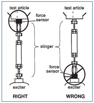
Stingers, sometimes also called quills, are required to perform modal testing with shakers. The shaker head should never be directly attached to the structure for modal testing. This would provide very poor frequency response measurements. If the shaker were to be directly attached to the structure, there would be significant dynamic effects of the shaker imposed onto the structure, resulting in a dramatically altered frequency response function.
Basically, the stinger decouples the shaker system from the structure and applies force to the structure. The stinger is designed to be rigid in the axial direction and flexible in the lateral direction. Force transducers measure axial force but still transmit forces into the structure through the transducers stiff casing. Therefore, any sideloads transmitted to the structure by the stinger through the force transducer are unmeasured and contribute noise on the measurement. A stinger that is properly designed, selected and aligned will reduce or eliminate this potential problem.
Of course the shakers dynamic subsystem will never be perfectly decoupled and there will practically always be some slight cross-axis force input to the structure. The intent of the stinger design is to be very stiff in the axial direction and extremely compliant to lateral loads to minimize this situation. The best stinger for minimizing any affects of cross-axis force input is a piano wire stinger, such at The Modal Shop model K2160G, which utilizes the through-hole armature design of a modal shaker allowing the wire to be pretensioned to push force into the test structure. The piano wire is completely flexible in the lateral direction, making it the optimal choice. Another alternative is a thin rod stinger design, such as The Modal Shop 2150G12, which also utilizes the through-hole armature design. Since this design is a stiff rod (rather than a wire) it does transmit some amount of force laterally. However, this style of stinger does not need to be pretensioned, and thus greatly simplifies setup. As a result it is more commonly used as an acceptable compromise of performance and ease-of-use.
The affects of the stinger assemblys lateral stiffness on the overall system is very dependent on the stiffness of the structure being tested. If the structure itself is stiff, then this is often not a serious concern. However, when the structure is flimsy or has a significant amount of rotational effect at the attachment point of the stinger then these lateral loads can become very important and a source of large measurement error. In addition, these rotational effects generally become more important at higher frequencies so it is always difficult to determine the actual impact on the overall results. One easy way to determine the effects of the stinger lateral and rotational effects is to make several test runs with the length of the stinger varying by +/- 10% and observe the change in the measured drive point frequency response.
Piano wire stingers are an excellent way to circumvent the problems with lateral stiffness associated with conventional stingers. Essentially the piano wire has no lateral stiffness to speak of. The piano wire is pretensioned with a load that is greater than the alternating load to be applied; a preload of 3 to 4 times the range is considered reasonable. The piano wire is fed through the core of the through-hole shaker armature; it is critical to have a modal shaker that is designed to accommodate this arrangement. A simple preload can be applied with weights or an elastic tie-down strap. With the weight applied, the collet is used to clamp the tensioned piano wire. As long as the applied load during shaker excitation is less that the preload, then the piano wire is an excellent way to transmit force and conduct a modal test, eliminating the effects of lateral stiffness in conventional stingers.
The length of the stinger can be an issue in performing a modal test. Given too short of a stinger, the structure will be less decoupled from the excitation system and there will be some dynamic effects of the shaker on the dynamics of the structure. Given too long of a stinger, the stinger will buckle within the frequency range of interest and insufficient force will be transmitted to the structure. The effects of this would be evident in the force transducers power spectrum measurement. Ideally, the stinger is set up to be as long as possible to maintain lateral flexibility but still short enough to transmit axial force without buckling.
The modal stingers are professionally made with the specific intent of being used for modal testing. They are intended to be used with modal shakers that are equipped with a through-hole armature design with a chuck and collet for clamping the stinger. The stinger can easily slide in the chucks collet until aligned and attached to the force transducer or impedance head, then tightened in place like a drill bit. The thin rod is very weak in the lateral direction, minimizing the transmission of transverse force inputs. The model 2150 series is just 1/16 diameter while the model 2155 series is 3/32 diameter, each with a 10-32 threaded stud brazed on the end to connect to the force transducer or impedance head attached on the test structure. An ordinary threaded rod with a conventional shaker (not specifically designed for modal testing) can be used, but set up and alignment are often difficult and cumbersome. Since these stinger designs are threaded throughout, attaching them to a tapped hole at both the test structure and the shaker armature, at the same time, is rather difficult. These are also typically much stiffer in the lateral direction, generating transverse force inputs, a significant source of measurement error.
The stinger is intended to be used to transmit force only along the axis of the stinger. It is very difficult to identify the exact level of inaccuracy that can be absorbed by a stinger. The thicker the stinger, the more misalignment it can physically support, but the more transverse force will be input into the system resulting in measurement error. The thinner the stinger, the more likely that any misalignment will bend the stinger, damaging it. However, since stingers are (relatively) inexpensive and intended to essentially be a mechanical fuse in your test setup, it is better to have an error in this direction. If you continue to bend stingers, damaging them beyond future use, it would follow that you have too much misalignment. At some point the quality of the measured data is suspect as well; however, this is dependent not just on the stinger but also on the structure under test and the frequency range to be considered.
(In a future updates of these FAQ, additional information with quantified example data will be provided for further understanding of this topic.)
The aluminum composite tube around the threaded rod is intended to provide additional stiffness to the stinger. Often times these are shipped together and they are installed and used as is for modal testing. Many times the aluminum composite tube provides too much lateral stiffness and may cause distortion of the measurement system. One way to determine the effect is to test the structure with and without the aluminum composite tube and further compare these results with a longer stinger configuration. If there is no difference in any of the measured drive point frequency response functions then there is no concern. But if there are differences, then assessment of the measured functions and which stinger system is most appropriate for the modal test needs to be identified.
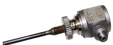
A very important consideration when mounting force transducers is recognition that force transducers are directional. This means that force transducers are designed to accurately measure force on only one of its two mounting faces, for example labeled TOP and BASE on the PCB model 208 series. This is shown below; a 208 series force transducer is mounted to a 2155G12 rod style stinger. Note that for this model force transducer the TOP of the unit is the designed sensing surface and should be mounted directly to the test article. Some transducers, like the PCB model 288D01 impedance head, have an indication of exactly which side to mount to the structure. In any case, please consult the force transducers user manual for identifying which mounting surface is intended to measure the force accurately. This is due to the fact that the force transducer itself has mass and stiffness. They are designed and calibrated to read force accurately on one of its mounting faces, and thus need to be installed accordingly.
Another important consideration is that the force transducer should always be mounted directly to the test structure, between it and the stinger and shaker assembly. If the force gage is mounted on the exciter side, then the dynamics of the stinger become part of the measured function. This is generally only an issue when using conventional shakers for modal applications because modal shakers have the through-hole armature design and would not accommodate mounting the force transducer in such a fashion.
The force transducer is usually mounted using a threaded adhesive mounting base, firmly attached to the test structure using dental cement or quick dry epoxy. Dental cement is ideal because it is extremely stiff, providing rigid attachment within the frequency range of typical modal testing. If the test structure can be drilled and tapped with an appropriate thread, directly attaching the force transducer to the structure is the best solution.
An impedance head, like PCB Piezotronics model 288D01, is a transducer that measures both force and resulting response in one device. Today, this is typically an accelerometer and force transducer but in the past it was a velocity transducer and force transducer (which is where the name impedance head comes from and has lingered on even today though velocity is rarely measured). This is a critical measurement in experimental modal analysis and it is recommended that impedance heads be used in most cases. A combination of a separate force transducer and accelerometer, mounted next to each other, is often used instead, but the convenience of measuring the driving point with a single transducer and validating reciprocity between input locations is best obtained with an impedance head.
The excitation levels for modal testing are usually reasonably low. There is no need to provide large force levels for conducting a modal test especially if appropriate response transducers (accelerometers) are selected with good sensitivity and resolution, as well as high quality, high resolution (24 bit technology standard in todays commercial offerings) data acquisition systems. The level only needs be sufficient enough to make good measurements. In fact, larger force levels tend to overdrive the structure, exciting nonlinear characteristics of the structure and providing poorer overall measurements than with lower level force tests. For this reason on larger structures, it is often desired to use multiple shakers at lower force levels to more evenly distribute force than a single shaker at a high level.
The number of shakers is often a difficult question to answer. Frequently we are limited by the total number of output sources in the data acquisition system or shakers available in the test lab for modal testing. Usually two to four shakers are sufficient for most tests, particularly when testing larger structures like automobiles or aircraft; tests with more than five shakers are rare. Ultimately, there need to be enough shakers acting as reference locations positioned so that all of the modes of the structure are adequately excited and observed and good frequency response measurements are obtained. This includes having multiple shaker/reference locations to resolve repeated roots and/or closely spaced modes.
The proper locations for shakers are heavily dependent on the frequencies and mode shapes to be extracted. Their location should be at points of adequate displacement in each of the modes of interest. It is common to perform pretest analysis using an impact hammer, like the PCB model 086 series, and an accelerometer to determine suitable active locations at each of the modes of interest. Impact hammers are very convenient because they provide hand-held freedom and flexibility to rove around the structure to test a large number of trial points to get an idea of the structural response. Then shakers can be set up at the necessary locations to adequately observe all of the modes simultaneously.
The location of the shaker is called the reference location for a modal test. If an inappropriate location is selected, then some of the modes may not be adequately excited and measured. This is another reason why multiple input shaker tests are conducted. But even with a MIMO test arrangement, much consideration needs to be given to the appropriate shaker reference locations. Suffice it to say that all of the modes need to be adequately excited by the reference location selected.
The main excitation technique used in modal testing today is burst random, used more often than others such as random, sine chirp and digital stepped sine. These are discussed with some brief comments. (Other techniques such as pseudo-random, periodic random, burst chirp and others are variations on these signals and are not discussed at length here.)
Random excitation was one of the first excitation techniques used because it was simple to create. The problem with random excitation is that the signal is never periodic in the sample interval of the FFT measurement and requires a window (commonly a Hanning window) to mediate the effects of leakage. Unfortunately, even with a window applied, the frequency response measurement suffers from leakage especially at the resonant peaks of the measurement.
Sine chirp is an excellent technique for testing systems that are fairly linear. This signal is a very fast swept sine where the frequency is swept from low frequency to high frequency within the time of one sample of the FFT analyzer. As a result, the signal is periodic in the sample interval once steady state response is achieved. This signal does not require any windows and does not suffer from leakage.
Burst random excitation was developed in the early 80s and has remained as one of the more commonly used excitation techniques for experimental modal testing. The vast majority of all shaker modal tests today employ burst random technique.
Burst random is formed as follows: A random excitation is generated but is only applied for a portion of the data block. In this way, the excitation signal is totally observable within one sample interval of the FFT analyzer and there is no need for the use of windows since there is no leakage associated with the captured signal. (Note: Providing that the response measured on the structure is also totally observable within one sample interval of the FFT analyzer then there is no need for the use of windows since there is no leakage associated with the captured signal.) However, once the excitation is turned off, the structural response will die exponentially depending on the damping associated with the structure. If the response of the structure does not die out within one sample interval, then the burst should be shortened such that the response does end before the end of the sample interval. The burst can be controlled by specifying the percentage of the block over which the excitation is to be applied. Generally, this can be accomplished with most structures.
Multiple Input Multiple Output (MIMO) testing requires the use of multiple shakers to excite the structure with uncorrelated signals supplied to each of the shakers. This requires that all the shakers be simultaneously attached to the structures for the modal test, as well as separate independent uncorrelated output sources from the data acquisition system.
While it seems possible to test the structure with one shaker and then move that shaker to all the different shaker locations, conducting the test in this manner typically results in an inconsistent set of frequency response functions. This can be due to a variety of reasons such as an inconsistent mass load distribution from roving transducers or environmental changes altering the structures mass and stiffness properties. When the different sets of data are combined, the resulting frequency responses are not as consistent as when all the data is collected simultaneously. The best measurement results have been achieved when all of the test data is acquired in a single snapshot, eliminating any issues related to time invariance or structure stationarity.
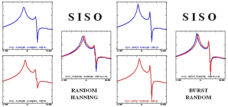
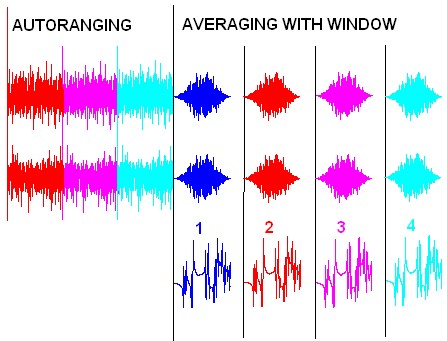
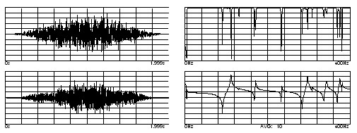
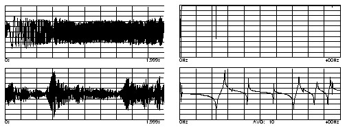
To illustrate this point, reciprocal frequency response measurements were taken with a single shaker moved between two different locations using a SISO approach. Each measurement was taken twice, first using a random and then a burst random signal to illustrate the differences. The results are shown below. Notice that the random signal has more variance and suffers from leakage even though a Hanning window was used. Clearly there is a difference in the two measurements shown; these two measurements should be exactly the same.
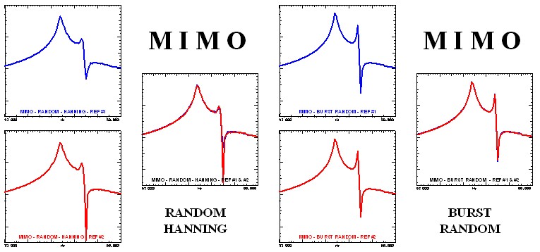
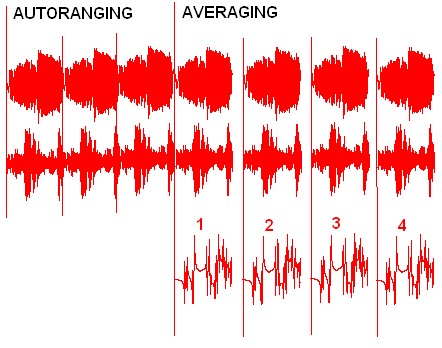
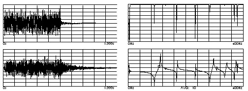
This measurement was repeated with a MIMO approach. Again a random excitation with a Hanning window and a burst random excitation were used. The variance using the random excitation can still be seen in the measurement even using the MIMO approach. Notice that the burst random MIMO approach provides the best measurement overall with a good frequency response where reciprocity is observed in the measurement.