Force Limited Vibration Testing Systems Rental

Prevent Vibration Overtesting | PCB 260 + 261 Series

Vibration overtesting occurs when an object under test is subjected to unrealistically severe and potentially damaging forces at the resonances of that object. Due to the high cost, long development times, and uniqueness of sophisticated aerospace and other high-tech equipment, it is important to implement techniques that prevent vibration overtesting and ensure the safety of such items during vibration qualification testing.

PCB's Force Limited Testing Systems provide the sensors that drive a closed loop control system to an existing shaker or slip table so that at frequencies where the measured force exceeds a safe limit, the controller’s output signal (input signal to the shaker) is “notched” by reducing output amplitude. Thus, reaction force between the test fixture and structure is maintained within specified limits, keeping the force experienced by the object under test within realistic and safe levels.

See the Environmental Test Brochure for detailed information on force limited vibration testing systems or the Force Sensors FAQ.

PCB Force Limited Vibration System Benefits:

  • Minimizes Over-testing
  • Reduces Risk of Damage to Critical Structures
  • Measures Summed Forces
  • Measures Force Differences (Moments)
  • Simplifies and Expedites the Test Process
  • Convenient and Easy to Implement

3-Component Quartz Force Sensors and Force Limited Vibration Test Equipment

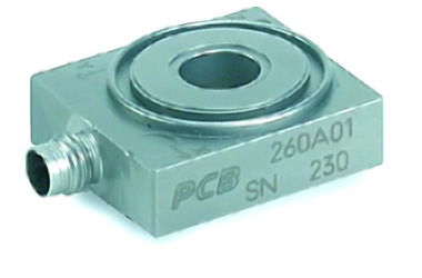
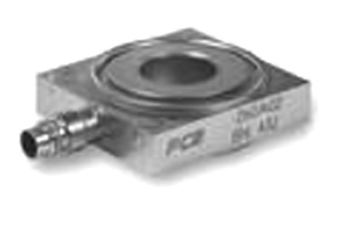
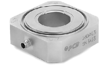
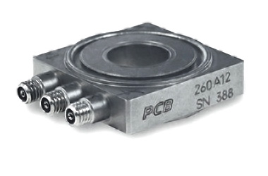
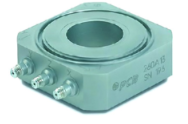
260 Series force ring sensors simultaneously measure dynamic force in three orthogonal directions (X, Y, and Z) and must be statically preloaded for optimum performance. Preloading provides the sensing elements with the compressive loading required to allow the proper transmission of shear forces. Versions are available in various ranges up to 10k lb (45k N) in the z-axis (perpendicular to the top surface), and up to 4000 lb (18k N) in the x-and y (shear) axes.

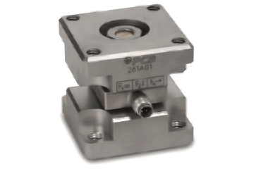
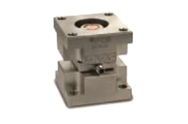
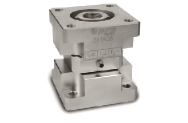
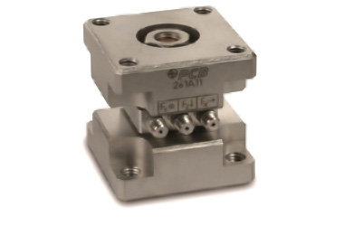
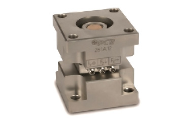
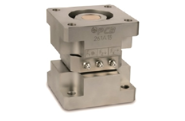
261 Series force links eliminate the preload requirement of 3-component quartz force ring sensors, and offer a convenient, 4-screw hole mounting plate on each side of the sensor. 261 Series units are constructed by installing a 3-component force ring sensor, under preload, between two mounting plates.

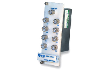
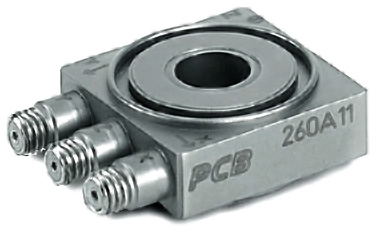
Both ICP® and charge output styles are available. ICP® sensors require only a single multi-conductor sensor cable and the low-impedance voltage system is ideal for for use in harsh industrial environments. Charge output 3-component force sensors operate with in-line charge converters or conventional laboratory-style charge amplifiers. Charge output styles are recommended for higher temperature applications and can be used for quasi-static measurements with long discharge time constant charge amplifiers, or when used with charge summing modules 070M69 or 070M70 below.

ModelSensor TypeMeasurement Range
(lb (kN))
Low Frequency
Response -5% (Hz)
Connector
Jack Type
Used Primarily With
Cable Type
z-axisx & y axesz-axisx & y axes
260A01/
261A01
ICP1 000 (4.45)500 (2.22)0.010.011/4-28 4-pin010G, 034G, or 078G
260A02/
261A02
ICP1 000 (4.45)1 000 (4.45)0.010.0011/4-28 4-pin
260A03/
261A03
ICP10 000 (44.5)4 000 (17.7)0.010.011/4-28 4-pin
260A11/
261A11
Charge1 000 (4.45)500 (2.22)(*)(*)(3) 10-32 jacks003G
(ends in 10-32)
003C
(ends in BNC)
260A12/
261A12
Charge1 000 (4.45)1 000 (4.45)(*)(*)(3) 10-32 jacks
260A13/
261A13
Charge10 000 (44.5)4 000 (17.7)(*)(*)(3) 10-32 jacks
260A31/
261A31
Charge**1 000 (4.45)500 (2.22)(*)(*)(3) 10-32 jacks
260A33/
261A33
Charge**10 000 (44.5)4000 (17.7)(*)(*)(3) 10-32 jacks

*Note: Resolution and low frequency response of charge mode triaxial force sensors is dependent on noise floor and discharge time constant characteristics of the signal conditioning and readout devices used. 422E series in-line charge converters allow 260 Series sensors to be powered with ICP conditioning.

**Note: Charge mode with reversed shear polarity.

Notes on cabling: Contact The Modal Shop for cable assistance. For many general purpose tests in lab conditions at or near room temperature, 010G, 034G, and 078G cables can be used interchangeably. A 2-digit suffix is added to Cable Types to denote length in feet: e.g., a model 010G20 cable mates to an ICP Force Sensor and terminates in 3x BNC, with a length of 20 ft.


Voltage/ICP Type to 1 000 lbf (z)


260A01

  • Hermetically sealed Stainless Steel housing
  • Though hole mounting via 5/16-24 beryllium-copper stud
  • 0.39” H x 1.075” L x 0.95” W
  • ±1000 lbf z axis, ±500 lbf x and y axis range
  • 1/4-28 4-pin jack used with 010G, 034G, or 078G series cable
  • Full specs from manufacturer
 

Rental Includes:

  • 081A70-Mounting stud, 5/16-24 UNF-2A typ each end
  • 082B02-Anti-Friction Washer
  • 083A10-Pilot Bushing
  • Calibration-NIST traceable and ISO 17025/A2LA accredited calibration; includes data to full scale operating range (PCB FCS-2). See notes on calibration for additional information

261A01 

  • Factory preloaded force link assembly using 260A01 sensor
  • Four screw hole mounting pattern on each side
  • ±1000 lbf z axis, ±500 lbf x and y axis range
  • 1/4-28 4-pin jack used with 010G, 034G, or 078G series cable

Voltage/ICP Type to 1 000 lbf (z)


260A02

  • Hermetically sealed Stainless Steel housing
  • Though hole mounting via 1/2-20 beryllium-copper stud
  • 0.39” H x 1.35” L x 1.25” W
  • ±1000 lbf range, all axes
  • 1/4-28 4-pin jack used with 010G, 034G, or 078G series cable
  • Full specs from manufacturer
 

Rental Includes:

  • 081A74-Pre-load bolt
  • 082M12-Anti-Friction Washer
  • 083A13-Pilot Bushing
  • Calibration-NIST traceable and ISO 17025/A2LA accredited calibration; includes data to full scale operating range (PCB FCS-2). See notes on calibration for additional information

261A02 

  • Factory preloaded force link assembly using 260A02 sensor
  • Four screw hole mounting pattern on each side
  • ±1000 lbf range, all axes
  • 1/4-28 4-pin jack used with 010G, 034G, or 078G series cable

Voltage/ICP Type to 10 000 lbf (z)


260A03 

  • Hermetically sealed Stainless Steel housing
  • Though hole mounting via 7/8-14 beryllium-copper stud
  • 0.79” H x 2.25” L x 2.25” W
  • ±10000 lbf z axis, ±4000 lbf x and y axis range
  • 1/4-28 4-pin jack used with 010G, 034G, or 078G series cable
  • Full specs from manufacturer
 

Rental Includes:

  • 081A70-Mounting stud, 5/16-24 UNF-2A typ each end
  • 082B02-Anti-Friction Washer
  • 083A10-Pilot Bushing
  • Calibration-NIST traceable and ISO 17025/A2LA accredited calibration; includes data to full scale operating range (PCB FCS-2). See notes on calibration for additional information

261A03 

  • Factory preloaded force link assembly using 260A03 sensor
  • Four screw hole mounting pattern on each side
  • ±10000 lbf z axis, ±4000 lbf x and y axis range
  • 1/4-28 4-pin jack used with 010G, 034G, or 078G series cable

Charge Type to 1 000 lbf (z)


260A11

  • Hermetically sealed Stainless Steel housing
  • Though hole mounting via 5/16-24 beryllium-copper stud
  • 0.39” H x 0.95” L x 0.95” W
  • ±1000 lbf z axis, ±500 lbf x and y axis range
  • (3) 10-32 coaxial jack electrical connector used with 002C or 003C series cables
  • Full specs from manufacturer
 

Rental Includes:

  • 081A70-Mounting stud, 5/16-24 UNF-2A typ each end
  • 082B02-Anti-Friction Washer
  • 083A10-Pilot Bushing
  • Calibration-NIST traceable and ISO 17025/A2LA accredited calibration; includes data to full scale operating range (PCB FCS-2). See notes on calibration for additional information

261A11

  • Factory preloaded force link assembly using 260A11 sensor
  • Four screw hole mounting pattern on each side
  • ±1000 lbf z axis, ±500 lbf x and y axis range
  • (3) 10-32 coaxial jack electrical connector used with 002C or 003C series cables

260A12

  • Hermetically sealed Stainless Steel housing
  • Though hole mounting via 1/2-20 beryllium-copper stud
  • 0.39” H x 1.25” L x 1.25” W
  • ±1000 lbf range, all axes
  • (3) 10-32 coaxial jack electrical connector used with 002C or 003C series cables
  • Full specs from manufacturer
 

Rental Includes:

  • 081A74-Pre-load bolt
  • 082M12-Anti-Friction Washer
  • 083A13-Pilot Bushing
  • Calibration-NIST traceable and ISO 17025/A2LA accredited calibration; includes data to full scale operating range (PCB FCS-2). See notes on calibration for additional information

261A12 

  • Factory preloaded force link assembly using 260A12 sensor
  • Four screw hole mounting pattern on each side
  • ±1000 lbf range, all axes
  • (3) 10-32 coaxial jack electrical connector used with 002C or 003C series cables

Charge Type to 10 000 lbf (z)


260A13 

  • Hermetically sealed Stainless Steel housing
  • Though hole mounting via 7/8-14 beryllium-copper stud
  • 0.79” H x 2.25” L x 2.25” W
  • ±10000 lbf z axis, ±4000 lbf x and y axis range
  • (3) 10-32 coaxial jack electrical connector used with 002C or 003C series cables
  • Full specs from manufacturer
 

Rental Includes:

  • 081A71-Mounting stud, 7/8-14 UNF-2A typ each end
  • 082B06-Anti-Friction Washer
  • 083A11-Pilot Bushing
  • Calibration-NIST traceable and ISO 17025/A2LA accredited calibration; includes data to full scale operating range (PCB FCS-2). See notes on calibration for additional information

261A13

  • Factory preloaded force link assembly using 260A13 sensor
  • Four screw hole mounting pattern on each side
  • ±10000 lbf z axis, ±4000 lbf x and y axis range
  • (3) 10-32 coaxial jack electrical connector used with 002C or 003C series cables

Reverse Shear Polarity Charge Type to 1 000 lbf (z)

Note: This sensor is the same as 260A11, except polarity is reversed for the x and y axes. This is useful for instrumenting a large test article with multiple force sensors on each side. Utilize half 260A11 and half 260A31 so all sensors have connectors in easily accessible locations.


260A31

  • Reversed Shear Polarity
  • Hermetically sealed Stainless Steel housing
  • Though hole mounting via 5/16-24 beryllium-copper stud
  • 0.39” H x 0.95” L x 0.95” W
  • ±1000 lbf z axis, ±500 lbf x and y axis range
  • (3) 10-32 coaxial jack electrical connector used with 002C or 003C series cables
  • Full specs from manufacturer
 

Rental Includes:

  • 081A70-Mounting stud, 5/16-24 UNF-2A typ each end
  • 082B02-Anti-Friction Washer
  • 083A10-Pilot Bushing
  • Calibration-NIST traceable and ISO 17025/A2LA accredited calibration; includes data to full scale operating range (PCB FCS-2). See notes on calibration for additional information

261A31

  • Reversed Shear Polarity
  • Factory preloaded force link assembly using 260A31 sensor
  • Four screw hole mounting pattern on each side
  • ±1000 lbf z axis, ±500 lbf x and y axis range
  • (3) 10-32 coaxial jack electrical connector used with 002C or 003C series cables

Reverse Shear Polarity Charge Type to 10 000 lbf (z)

Note: This sensor is the same as 260A13, except polarity is reversed for the x and y axes. This is useful for instrumenting a large test article with multiple force sensors on each side. Utilize half 260A13 and half 260A33 so all sensors have connectors in easily accessible locations.


260A33

  • Reversed Shear Polarity
  • Hermetically sealed Stainless Steel housing
  • Though hole mounting via 7/8-14 beryllium-copper stud
  • 0.79” H x 2.25” L x 2.25” W
  • ±10000 lbf z axis, ±4000 lbf x and y axis range
  • (3) 10-32 coaxial jack electrical connector used with 002C or 003C series cables
 

Rental Includes:

  • 081A71-Mounting stud, 7/8-14 UNF-2A typ each end
  • 082B06-Anti-Friction Washer
  • 083A11-Pilot Bushing
  • Calibration-NIST traceable and ISO 17025/A2LA accredited calibration; includes data to full scale operating range (PCB FCS-2). See notes on calibration for additional information

261A33

  • Reversed Shear Polarity
  • Factory preloaded force link assembly using 260A33 sensor
  • Four screw hole mounting pattern on each side
  • ±10000 lbf z axis, ±4000 lbf x and y axis range
  • (3) 10-32 coaxial jack electrical connector used with 002C or 003C series cables

Chassis and Power Modules


441A49 Overview

441A49 

  • 9-slot slave chassis for PCB 440 Series signal conditioning modules

441A101 product on White Background

441A101 

  • AC power module for the 440 series Modular Signal Conditioners.

443B102

  • Dual Mode single channel amplifier for ICP® and charge output sensors
  • Able to be DC coupled to allow the preload of 260 series force sensors to be set during installation
  • Includes selectable gain, discharge time constant, and high and low pass filters
  • Requires chassis (441A39) with power supply (441A101)
  • Full specs from manufacturer

070M69

  • Computational Signal Conditioner computes the difference and outputs up to four pairs of signals
  • Provides output summation of the differences
  • Can be used with voltage signals or supplies constant current excitation for ICP® sensors
  • 0.1x, 1x, 10x gain
  • 8 BNC input
  • 4 BNC differenced outputs, one BNC summed difference output
  • Requires chassis ( 441A39) with power supply ( 441A101)
  • Full specs from manufacturer

070M70

  • Charge Summing Patch Panel allows the addition of up to eight charge inputs and sums them to provide one charge output
  • 8 BNC inputs
  • 1 BNC output
  • Summed output (A + B + C + D + E + F + G + H)
  • Requires chassis ( 441A39)
  • Full specs from manufacturer

070A15 

  • Charge Summing block
  • (4) 10-32 jack inputs to (1) BNC output
  • for use with charge output sensors only
  • Typical Use: Measuring force over a large surface area using a plate with one force sensor under each corner. Sums force signals and sends resulting summed charge signal to single charge amplifier
  • Requires chassis (441A39)
  • Full specs from manufacturer