Main Menu
- Home
- Product Finder
- Calibration Systems
- Calibration Services
- Digital Sensing
- Industrial Vibration Calibration
- Modal and Vibration Testing
- Non-Destructive Testing
- Sound & Vibration Rental Program
- Learn
- About Us
- Contact Us
In this month’s article, we will discuss microphone calibration using the insert voltage technique to calculate the open circuit sensitivity of a precision condenser microphone. Let us first define open circuit sensitivity before explaining how to calculate it. The open circuit voltage of a microphone, according to IEC 1094-1, is the unloaded alternating voltage as measured at the electrical output terminals of the microphone. The open circuit sensitivity of a microphone is the ratio of the microphone’s open circuit voltage to the sound pressure level applied to the microphone by a sound source. Because it is impractical to measure the open circuit voltage from a microphone directly at its electrical terminals, the insert voltage technique (as described in section 5.3 of IEC 1094-2) must be applied.
The equipment required to perform an open circuit sensitivity calibration is: a calibrated reference standard microphone, a specialized preamplifier with insert voltage capability, a sound source (either a speakerphone or pistonphone which outputs a stable sound pressure signal at reference frequency - typically 250 Hz), and the microphone to be calibrated. The reference standard microphone should be calibrated by an external laboratory using an accredited and traceable process. The calibrated sensitivity of the reference standard microphone is typically very stable regardless of changes in ambient pressure and temperature. The sound pressure level output by the sound source is susceptible to changes in environmental conditions and is, therefore, used as a transfer standard to compare the test microphone’s output to the output of the controlled reference microphone.
The first step to performing an open circuit voltage calibration is to measure the sound source/sound pressure output signal using the known sensitivity of the reference standard microphone. We apply the sound source to the reference microphone, which is mounted to the insert voltage preamplifier, and measure the reference microphone response to the sound source. Because the microphone signal is loaded with the impedance of the preamplifier, and we would like to measure the microphone’s open circuit voltage, the second step is to remove the sound source and apply a voltage signal (of the same frequency as the sound source) through the insert voltage (or calibration) input of the preamplifier and into the reference microphone.
This insert voltage signal effectively “inserts” an alternating electrical calibration signal across the microphone’s capacitive sensing element, changing the capacitance between the diaphragm and backplate of the microphone, and drives a response from the microphone. The reference microphone’s response to the insert voltage signal is measured through the same electrical path as the sound source signal. The amplitude of the insert voltage signal is measured and adjusted until the microphone output signal is equal to the reference microphone's response to the sound source. When the reference microphone’s response to the insert voltage signal is equal in amplitude to the reference microphone response to the sound source, the amplitude of the insert voltage signal is the open circuit voltage of the reference microphone. Since the sensitivity of the reference microphone is already known, the sound pressure level of the sound source (in Pascals) is easily calculated using the following formula.

Once the sound pressure level of the sound source is known, the same process is repeated with the test microphone mounted on the insert voltage preamplifier in place of the reference microphone. The sound source is applied to the test microphone and we record the response of the test microphone loaded by the impedance of the preamplifier. Next we remove the sound source, apply the insert voltage through the preamplifier into the test microphone, and adjust the amplitude of the insert voltage signal until the test microphone’s response to the insert voltage signal is equal to the test microphone’s response from the sound source. As with the reference microphone, when the amplitude of the test microphone’s response to the insert voltage signal is equal to the test microphone’s response from the sound source, the amplitude of the insert voltage signal is measured and is equal to the open circuit voltage of the test microphone. Once the open circuit voltage has been measured, the open circuit sensitivity of the test microphone at the reference frequency is calculated using the following formula.

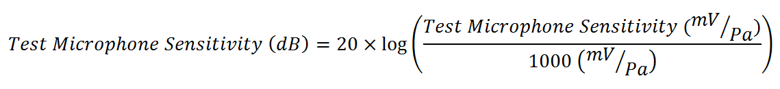
After calculating the open circuit sensitivity of the test microphone (in mV/Pa), it is very easy to perform a quick conversion to the standard microphone sensitivity unit of decibels (dB). The standard for microphones is to use 1V per Pascal as the reference value for dB conversion. Notice that the open circuit sensitivity is reported in mV/Pa, and the reference value is 1 V/Pa. To properly cancel the units for the dB conversion, we need to use 1000 mV/Pa as the reference value. The formula below shows how to calculate the test microphone sensitivity in dB.