Main Menu
- Home
- Product Finder
- Calibration Systems
- Calibration Services
- Digital Sensing
- Industrial Vibration Calibration
- Modal and Vibration Testing
- Non-Destructive Testing
- Sound & Vibration Rental Program
- Learn
- About Us
- Contact Us
In the early days of vibration measurement and calibration, users were plagued by a calibration conundrum that supposedly identical input to accelerometers placed next to each other (or even on top of each other!) on a controlled shaker gave different responses. What at first glance seemed to be a contradiction, quickly began to show what we clearly know now: dynamics occur in ALL structures of ALL sizes.
Looking at the problem in more detail, we can examine why “identical” sensor mounts give different responses. First and foremost, remember that nothing is perfectly rigid nor is anything perfectly designed or constructed. In the case of an electrodynamic exciter, the basic operation entails applying an electrical drive signal (voltage) representative of the desired output response (force and motion). The wound armature rides along a bearing and typically has a flexure or support to carry the weight of the armature itself along with a basic payload. By now, you can see that the construction of the device is mechanically complex with magnets, windings, bearings, flexures, a housing and a mounting surface. The result is a system that primarily provides uniaxial excitation, but in performance also has its own unique resonant frequencies and vibration mode shapes (some vertical, some lateral and some torsional). Accordingly, at certain frequencies of operation, the mounting surface can actually be rocking or sliding sideways at higher amplitudes than the desired primary axis of motion. Unless great care is taken in design and fabrication of a shaker, this is how excitation structures naturally behave. The extra degrees of freedom of motion (both transverse as well as off centered pitch and roll) cause extraneous signal output to different degrees (depending on alignment of minimum/maximum transverse sensitivity of the sensors, as well as their tangential component of acceleration due to the rocking) in side-by-side vibration measurements. For this, simultaneous calibration of groups of side-by-side accelerometers on a platform has been impractical for any calibration frequency response measurements. (This technique can be used for certain single frequency point calibrations in ideal ranges and can also be used in a global sense for the frequency range less than 2000 Hz if an array of calibration reference accelerometers is used to measure all six degrees-of-freedom of a custom designed rigid mounting platform.)
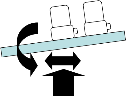
Figure 1: Side by side accelerometer comparison shows different output
In the case of stacking accelerometers, dynamics immediately become a challenge. Fundamentally, the acceleration measured at the mounting surfaces are different due to the different loads, the stiffness of the mounting means and any dynamics of the accelerometer casing on which the second accelerometer is mounted.
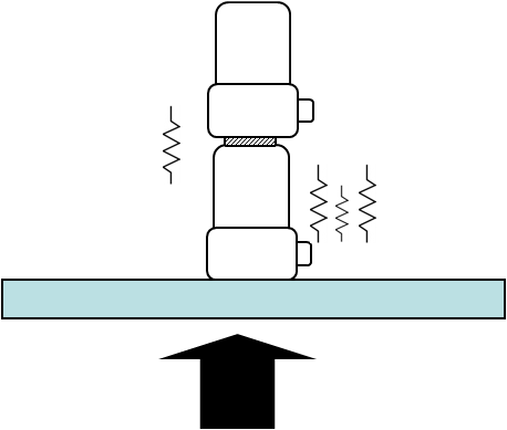
Figure 2: Accelerometer mounted on top of another accelerometer. Additional dynamics exist in mounting means and lower accelerometer casing.
The solution to both these challenges was addressed very simply and mechanically, as it often was in the early days of measurement systems. Designing an inverted compression mode piezoelectric accelerometer accomplished the first key of measuring the identical acceleration at the same surface. The compression design provides a high mounted natural frequency for a wide useful frequency response. By “hanging” the internal sensing structure from the top interface of the reference standard accelerometer, the design ensures that the reference “sees” the same acceleration as the sensor under test (SUT) being calibrated.
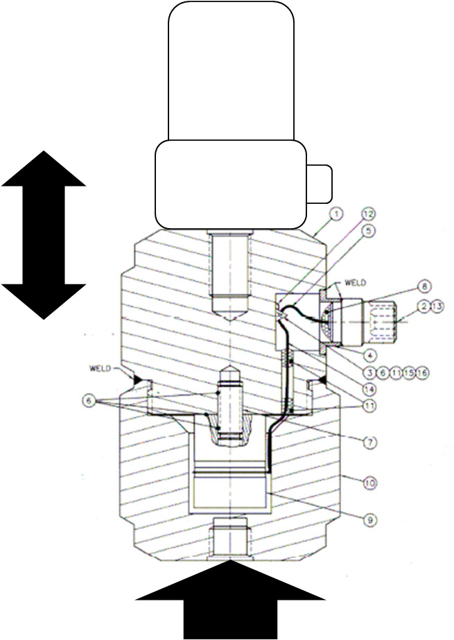
Figure 3: Inverted compression mode ICP® Calibration Standard Reference accelerometer. Both sensors measure the acceleration at the joined interface.
The first generation of accelerometers contained sensing crystals providing a high impedance charge signal which then needed to be conditioned and converted to low impedance by a charge amplifier. Since old readout/recording instruments varied greatly, it was sometimes necessary to handle the appropriate signal ranging on the charge amplifier. For users, the cost of the laboratory charge amplifiers was high and the high impedance signal coming from the reference accelerometer was susceptible to noise through either cable whip (tribo-electric effect) or through loss of insulation resistance caused by dirt and finger oil across the signal path connectors and cables. Accordingly, great care was taken to minimize cable lengths, providing strain relieving service loops and securing loose segments while also keeping the measurement equipment and environment clean.
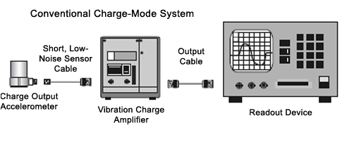
Figure 4: Charge amplifier setup
As state-of-the-art electronics progressed, the advent of the Field Effect Transistor (FET) provided a new opportunity for simplification in the piezoelectric measurement industry. By incorporating either a MOSFET or JFET transistor internal to the sensing element, it was possible to collect the high impedance charge generated by the piezoelectric crystals and convert it to a low impedance voltage output. The simple yet elegant solution required an excitation voltage through a constant current diode and coupling capacitor to remove the DC bias. The benefits of constant current ICP® internal impedance conversion are legendary. There was no opportunity for cable whip to introduce tribo-electric noise and the electronics were sealed hermetically into the sensor package, ensuring long term stability. The ICP low impedance mode inverted compression reference sensor had all the benefits of the original charge design (measuring at the same mechanical interface and high natural frequency/useable frequency range).
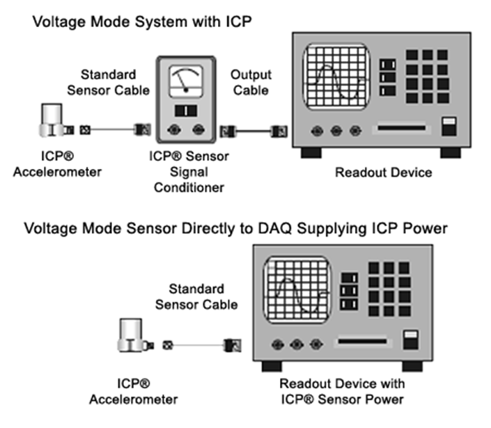
Figure 5: Modern ICP accelerometer channel
Further improvements to the internal electronic ICP inverted reference accelerometer design were later made, incorporating a shear structured sensing element to provide additional rejection for environmental influences and mechanical strain. While the inverted shear design did not provide as wide a frequency range, it proved to be ideal for the higher sensitivity low frequency reference accelerometer in uses as low as 0.5 Hz. This was an added benefit to reduce uncertainties in high amplitude shaker environments that could be thermally active.
An additional concern arises with large low frequency accelerometers and specialized mounts such as aircraft engine monitoring accelerometers. The traditional center hole threaded mount is no longer sufficient. A variety of complex mounting bolt patterns accommodate low frequency and airborne accelerometers. As a further complication, custom mounting brackets can be needed to orient the sensitive axis of the SUT and align with the axis of motion of the calibration exciter and reference. These types of accelerometers are impractical to support and mount on a traditional reference accelerometer.
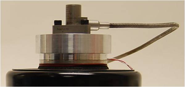
Figure 6: Aircraft engine monitoring accelerometer with triangular mounting bolt pattern
To accommodate the broadest variety of accelerometer sizes and mounts, modern calibration grade exciters have been carefully designed with a mounting insert which incorporates an extremely high performance, light weight, integral reference accelerometer. While sometimes constructed from aluminum (useful for only lower frequency ranges), the most widely adopted, highest performance for precision calibration excitation mounting inserts are designed and fabricated from aerospace grade beryllium. The combination of material stiffness and low weight provide the highest useable frequency range and most SUT payload for a given exciter. The integrated reference accelerometer is also a shear design for improved thermal characteristics. It maintains an extremely small size for the highest possible mounted resonant frequency to facilitate the SUT resonance search feature in calibration systems.
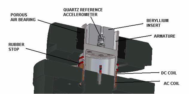
Figure 7: Beryllium insert with imbedded ICP reference accelerometer in state-of-the-art precision air-bearing calibration exciter
Research in calibration carries on. New materials and electronics are arriving every day. However, when it comes to metrology, new technology must earn its place in calibration systems. When selecting new equipment, it is wise to ask your vendor for at least a year’s worth of validation data and detailed uncertainty updates, including comparisons to national laboratories. Calibration is certainly about control and confidence… so, as always, click or call to connect with us if you have any questions.