Main Menu
- Home
- Product Finder
- Calibration Systems
- Calibration Services
- Digital Sensing
- Industrial Vibration Calibration
- Modal and Vibration Testing
- Non-Destructive Testing
- Sound & Vibration Rental Program
- Learn
- About Us
- Contact Us
 ICP sensors require a constant current power source providing 2 to 20 mA at 18 to 28V DC. In most applications, 2 to 4 mA current is adequate. In
special applications driving long cables (>100ft) at high frequencies (100k Hz), higher current is required to avoid high frequency attenuation. For specifics, please view the driving ICP sensors over long cables reference nomograph.
ICP sensors require a constant current power source providing 2 to 20 mA at 18 to 28V DC. In most applications, 2 to 4 mA current is adequate. In
special applications driving long cables (>100ft) at high frequencies (100k Hz), higher current is required to avoid high frequency attenuation. For specifics, please view the driving ICP sensors over long cables reference nomograph.
Do not apply a DC voltage directly to an ICP sensor with either a power supply or a voltmeter. Applying DC voltage directly to the ICP sensor, without current limiting, can damage the sensor’s internal electronics.
Unlike high impedance charge mode sensors, checking the impedance across the connector pin to ground of an ICP sensor with a dmm will not provide meaningful information. Consult the information above to avoid damage to the ICP sensor’s built-in electronics.
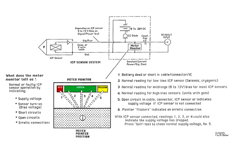
To check operation of an ICP sensor, connect the sensor to a PCB power/signal conditioner that has a circuit integrity meter monitor which can display sensor bias voltage or perhaps bias LED indicators on newer products.
When an ICP sensor is connected to a PCB constant current power unit through a good cable, the meter will indicate normal sensor bias voltage of 9 to 13V (Mid Green), or around 3 to 8V (Lower Green) for some low bias sensors (seismic, cryogenic and certain low noise models), or 14 to 17V (High Green) for sensors with built-in circuit gain.
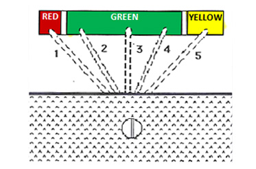
DMM and Color coded meter readings for various sensor bias voltages and cable connections are indicated below:
| Sensor Bias | DMM Reading | Color Coded Analog Meter |
|---|---|---|
| Most ICP Sensors | 9 to 13V | "GREEN" (Mid Scale) |
| Low Bias ICP Sensors | 3 to 8V | "GREEN" (Low End) |
| High Bias ICP Sensors | 14 to 17V | "GREEN" (High End) |
| Cable open circuit* | 24 to 28V | "YELLOW" (Full Scale) |
| Shorted cable* | 0 Volts | "RED" (Low End) |
*Install new cable (or remove old cable and check end-to-end continuity of center conductor and shield with a DMM). Be sure when connecting the cable to the sensor to turn the cable’s floating connector and do not turn the sensor. Turning the sensor may cause shavings off the center pin causing shorts or alternatively the cable connector pin to catch and also rotate tearing free of its wiring connection and cause an “open” in the circuit.