Main Menu
- Home
- Product Finder
- Calibration Systems
- Calibration Services
- Digital Sensing
- Industrial Vibration Calibration
- Modal and Vibration Testing
- Non-Destructive Testing
- Sound & Vibration Rental Program
- Learn
- About Us
- Contact Us
A frequent calibration question we receive here at The Modal Shop, Inc. is: “Should I bolt my shaker to a heavy table?” The difference in answer depends on which reference you are using with the shaker. For back-to-back calibration, we typically answer “no;” for optical encoder calibrations we typically answer “yes.” The reason we require bolting a shaker with an encoder displacement reference to a table or large mass is reference motion, often called relative motion.
Relative motion can occur when the reference sensor is decoupled from the test sensor as is the case with optical encoder-referenced calibrations. When the reference sensor is subject to an external force (such as the reactionary force of shaker armature motion) or from any external source of vibration that can be transmitted to the base of the calibration shaker (such as building foot traffic or a nearby highway or train), relative motion error will present itself as a change in measured sensitivity with a change in the motion of the reference. For the purposes of this article, all relative motion of the reference is assumed to be without any transverse component (purely vertical).
In optical encoder calibration, relative motion will cause error in the sensitivity calculation. This is because optical encoder references measure acceleration (of the Sensor Under Test) relative to the motion at another point (at the reference). This is the motion of the optical read head relative to the reflective scale tape.
In the example in Figure 1, the optical reference (read head) is rigidly attached to the shaker body, with the reflective scale tape surface located at the Sensor Under Test (SUT)/ shaker armature. In an ideal situation, the shaker body is motionless (AR=0) and the optical read head gives a value of motion of the shaker armature and SUT relative to the stationary read head. This situation is best achieved in practice by rigidly bolting the shaker to a heavy seismic mass so that the shaker reactionary motion (recoil) is proportionally much smaller than the test excitation (AT).
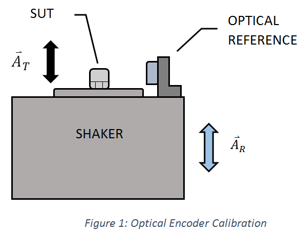
In a non-ideal situation, the shaker is mounted to a low stiffness base such as a thick rubber pad. In this situation, the shaker body performs like a mass spring damper system with a resonance low enough to cause large motion at some test frequencies (AR>0). One of the easiest ways to think about this error is to imagine a situation in which the shaker armature was to remain completely motionless, and the shaker body was vibrating at 1 g. In this situation, the test accelerometer would have no output (the armature is not moving), and the optical reference would be measuring 1 g of motion because it is moving relative to the armature (100% error). In practice, the situation would never be this severe. Any motion of the base (AR) directly produces relative motion error when using a relative measurement technique such as an optical encoder.
So why is back-to-back calibration immune to relative motion of the shaker base? In Figure 2, relative motion is represented as AR, the vertical motion of the shaker base. The test acceleration is represented as AT.
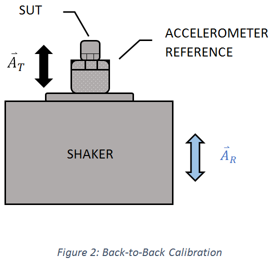
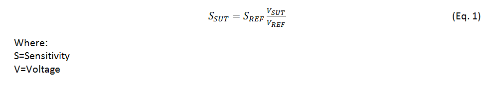
In back-to-back accelerometer calibration, the relative motion base does not affect the calibration result because relative motion of the base would cause an acceleration change in both the reference (REF) and the Sensor Under Test (SUT) equally. This change in acceleration would cause a proportionally equal change in voltage from the REF and SUT, and in calculating sensitivity, the change in voltages cancel in the voltage ratio (Eq. 1).
In optical-referenced calibrations, it is important to consider the effect of the relative motion of your reference on the uncertainty of the calibration. A very simple way to measure relative motion is to affix an accelerometer to the shaker base and monitor the peak acceleration while running a calibration sweep. The amount of acceleration of the instrumented accelerometer relative to the test level is your relative motion error.
Keep in mind that when interpreting the instrumented accelerometer data, the acceleration value you read from this sensor is also frequency dependent. If your calibration method is employing the use of a Fourier Transform to interpret the data, any relative motion at frequencies other than the test frequency will be effectively canceled. This means that when calculating the uncertainty component for relative motion, the error component does not have to be the maximum motion across the operating frequency range. Instead, the error contribution can be set at different levels if you break up your stated uncertainty into different frequency ranges.
An important distinction to reiterate is that relative motion is not the same as transverse motion. If lateral (transverse) motion of the shaker were present, it would cause a different calibration error which is explained further here: How Does Transverse Motion Affect Accelerometer Calibration Results?