Main Menu
- Home
- Product Finder
- Calibration Systems
- Calibration Services
- Digital Sensing
- Industrial Vibration Calibration
- Modal and Vibration Testing
- Non-Destructive Testing
- Sound & Vibration Rental Program
- Learn
- About Us
- Contact Us
 Accelerometer Basics
Accelerometers are inertial transducers that can sense mechanical motion and convert it into an electrical quantity that may be conveniently measured or recorded. The accelerometer, either alone or with other electrical components, produces an electrical output signal related to the applied motion. Accurate accelerometer calibration is a way to provide physical meaning to this electrical output and it is a prerequisite for quality measurements.
Calibration Basics
The manufacturer of an accelerometer subjects the design to a wide variety of tests to determine output due to a large number of inputs. Output characteristics commonly measured include sensitivity, frequency response, resonant frequency, amplitude linearity, transverse sensitivity, temperature response, time constant, capacitance, and the other environmental effects (base strain sensitivity, magnetic sensitivity, etc).
Vibration Calibration
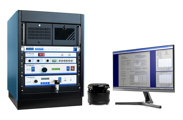
A subset of these parameters is typically tested in a dedicated ‘back-to-back’ calibration system for laboratory use. Computer controlled accelerometer calibration workstations not only automate the sometimes tedious calibration process but also help minimize human errors, enhancing system repeatability and accuracy.
Comparison methods are normally performed by back-to-back measurements against a reference standard to measure sensitivity, linearity, frequency and phase response. The sensor under test (SUT) is mounted in a back-to-back arrangement with a standard reference accelerometer (the reference having traceability to primary calibration). Since the motion input is the same for both devices, the ratio of their outputs is also the ratio of their sensitivities and the sensitivity Ssut of the SUT can be calculated as:
Ssut = Sref x (Vsut / Vref) x (Gref / Gsut)
Sref is the reference transducer sensitivity
Vsut is the SUT output (in mV or pC)
Vref is the reference sensor output (in mV or pC)
Gsut is the SUT gain (in mV/mV or mV/pC)
Gref is the reference gain (in mV/mV or
mV/pC)
Both sensors can be mounted to an electrodynamic shaker driven with a sinusoidal vibration and the sensitivity of the SUT is measured at that particular frequency. Sweeping through the desired range of frequencies then generates a frequency response curve of the SUT.
Air bearing shakers are the preferable type of electrodynamic shaker to be used, as they can provide the highest quality of pure single degree of freedom vibration over the widest frequency range, while minimizing the transverse motion and distortion found on other electrodynamic shakers.
Shock Calibration
One limitation of most electro-mechanical shakers, however, is that the acceleration levels possible are inadequate for the complete calibration of low sensitivity accelerometers designed for shock applications.
Shock accelerometers are specifically designed to withstand and measure extreme, high amplitude, short duration accelerations often associated with transients. Such accelerations characteristically exceed the range limit found on other typical vibration accelerometer designs. Several applications for shock accelerometers are found in the areas of automotive engineering and human safety, aerospace, military and weapons applications, package and drop testing, pyroshock events and explosive studies, projectile impacts, etc.
Transient accelerations can be very large, possibly stressing the sensors to non-linear regions of operation. It is highly desirable to test the accelerometers at levels typical of the actual measurement. In general, shock acceleration events may easily exceed 5,000 gn or more with pulse durations of less than 10 ms (1 gn = 9.80665 m/s2). Many test laboratories will shock calibrate each sensor before and after every test to check if the transducer survived and to validate the acquired data.
Since the acceleration levels available on calibration quality shakers are not adequate to test shock accelerometers at full scale levels, different techniques are needed. ISO 16063-22 specifically describes instrumentation and procedures to be used for secondary shock calibration of accelerometers, using a reference acceleration, velocity or force measurement for the time dependent shock comparison. The methods are applicable in a shock pulse duration range of 0.05 ms to 8.0 ms, and a dynamic range (peak value) of 10 gn to 10,000 gn (time dependent). The resulting data allow the transducer shock sensitivity to be obtained.
A pneumatic shock system can perform calibration and linearity checks up to 10,000 gn and is one of the most versatile anvil shock type devices available for shock calibration (in terms of amplitude range, pulse duration, repeatability, and traceability to primary calibration methodologies).