Main Menu
- Home
- Product Finder
- Calibration Systems
- Calibration Services
- Digital Sensing
- Industrial Vibration Calibration
- Modal and Vibration Testing
- Non-Destructive Testing
- Sound & Vibration Rental Program
- Learn
- About Us
- Contact Us
Shock and vibration phenomena are present around us in everything that moves. If something moves, it experiences acceleration. Measurement of this acceleration helps us gain a higher understanding of the nature of the motion. Understanding that increases our awareness of an event or encourages refinement of the engineering design of a moving device.
Accelerometers are sensors that can sense mechanical motion of the attached structure and convert it into an electrical quantity that may be conveniently measured or recorded. The accelerometer, either alone or with other electrical components, produces an electrical output signal related to the applied motion. Accurate accelerometer calibration is a way to provide physical meaning to this electrical output and it is a prerequisite for quality measurements.
The manufacturer of an accelerometer subjects the design to a wide variety of tests to determine output due to a large number of inputs. Output characteristics commonly measured include sensitivity, frequency response, resonant frequency, amplitude linearity, transverse sensitivity, temperature response, time constant, capacitance and the other environmental effects (base strain sensitivity, magnetic sensitivity, etc).
A subset of these parameters is typically tested in a dedicated “back-to-back” calibration system for laboratory use as shown in Figure 1. Computer-controlled accelerometer calibration workstations not only automate the sometimes tedious calibration process but also help minimize human errors and enhance system repeatability and accuracy.
Comparison methods are normally performed by back-to-back measurements against a reference standard to measure sensitivity, linearity, frequency and phase response.2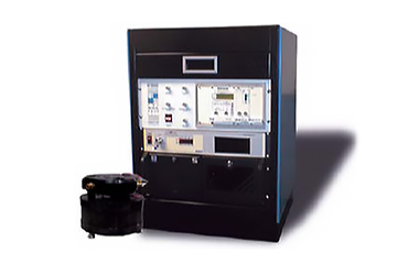
Figure 1. Accelerometer calibration workstation next to an electrodynamic air bearing calibration shaker.
The sensor under test (SUT) is mounted in a back-to-back arrangement with a standard reference accelerometer, the reference having traceability to primary calibration. Since the motion input is the same for both devices, the ratio of their outputs is also the ratio of their sensitivities, and the sensitivity Ssut of the SUT can be calculated as:
Ssut = Sref (Vsut /Vref )(Gref /Gsut )where:
Sref = reference transducer sensitivity
Vsut = SUT output (mV or pC)
Vref = reference sensor output (mV or pC)
Gsut = SUT gain (mV/mV or mV/pC)
Gref =
reference gain (mV/mV or mV/pC)
Both sensors can be mounted to an electrodynamic shaker driven with a sinusoidal vibration and the sensitivity of the SUT is measured at that particular frequency. Sweeping through the desired range of frequencies then generates a frequency response curve for the SUT.
Air-bearing shakers are the preferable type of electrodynamic shaker to be used, as they can provide the highest quality of pure single degree of freedom vibration over the widest frequency range, while minimizing the transverse motion and distortion found on other electrodynamic shakers.3 However, one limitation of most shakers is that the acceleration levels possible are inadequate for complete calibration of low-sensitivity accelerometers designed for shock applications.
Shock accelerometers are specifically designed to withstand and measure extreme,high-amplitude, short-duration accelerations often associated with transients. Such accelerations characteristically exceed the range limit found on other typical vibration accelerometer designs. Several applications for shock accelerometers are found in the areas of automotive engineering and human safety (Figure 2), aerospace, military and weapons applications, package and drop testing, pyroshock events and explosive studies, projectile impacts, etc.
Transient accelerations can be very large, possibly stressing the sensors to nonlinear regions of operation. It is highly desirable to test the accelerometers at levels typical of the actual measurement. In general, shock acceleration events
may easily exceed 5,000 g or more with pulse durations of less than 10 ms (1 g = 9.80665 m/s2). Many test laboratories will shock calibrate each sensor before and after every test to check if the transducer survived and to validate
the acquired data.
 Since the acceleration levels available on calibration-quality shakers are not adequate to test shock
accelerometers at high levels, different techniques are needed. ISO 16063-22 specifically describes instrumentation and procedures to be used for secondary shock calibration of accelerometers, using a reference acceleration,
velocity or force measurement for the time-dependent shock comparison.4 The methods are applicable in
Since the acceleration levels available on calibration-quality shakers are not adequate to test shock
accelerometers at high levels, different techniques are needed. ISO 16063-22 specifically describes instrumentation and procedures to be used for secondary shock calibration of accelerometers, using a reference acceleration,
velocity or force measurement for the time-dependent shock comparison.4 The methods are applicable in
a shock pulse duration range of 0.05 to 8.0 ms, and a dynamic range (peak value) of 10 10,000 g (time dependent). The resulting data allow the transducer shock sensitivity to be obtained.
An example of the most common shock testing device, a pneumatic shock exciter,is shown in Figure 3. This system can perform calibration and linearity checks up to 10,000 g and is one of the most versatile anvil shock-type devices available for shock calibration in terms of amplitude range, pulse duration, repeatability, and traceability to primary calibration methodologies.
In this exciter, a regulated air pressure drives a projectile to impact an ‘anvil’ to which transducers are mounted (Figure 4). A pilot-operated poppet valve is used to quickly release the controlled pressure, which controls the amount of linear momentum transfer in an impact. Pressure pulse duration and level can be finely tuned to provide precise control and adjustment of the projectile shock levels. An assortment of anvils with different padding stiffness characteristics is available to adjust acceleration and pulse duration resulting from the impact. The anvil assembly is inserted into the guide at the end of the barrel in which a projectile is launched. A mechanism with ‘fingers’ slides over the assembly, which catches the transducers during their upward flight. Each finger mechanism has an interlock safety switch that disables the system if it is not in position.
Printed calibration certificates fulfilling the requirements set forth by ISO 17025 can be easily generated, and calibration results can be stored in open database format for ease of retrieval and data management.
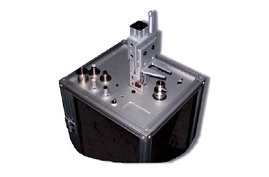
Figure 3. 9155C-525 pneumatic shock exciter.
The system can also test accelerometers for other characteristics, such as zero shift, ringing and nonlinearity. Figure 5 shows a typical screen shot of the measured shock and the calibration results produced with the pneumatic exciter described above.
A time-domain polynomial approximation of the shock pulses is performed according to ISO-16063-22 to calculate peak output values of the two sensors. The sensitivity value for the SUT is calculated using the equation described previously.
Other methods of shock calibration include well-described Hopkinson bar systems, which are particularly suitable for testing sensors under extremely high shock levels normally ranging from 10,000-200,000 g.![]()
Figure 4. Test transducer, reference transducer, and anvil mounting arrangement.
A previous article5 published in this magazine provides very good details on the Hopkinson bar calibration method. ISO 16063-22 mentions the Hopkinson bar method, but a maximum level of 10,000 g is specified, which has reference to primary methodologies (see ISO 16063-13 for details6). Last but not least, pendulum and drop-ball apparatus are also described in ISO 16063-22 and can alternatively be used for shock calibration.

Figure 5. Calibration output results for a shock sensor tested from 2,000-10,000 g acceleration levels.
1. www.modalshop.com
2. ISO 16063-21, Methods for the Calibration of Vibration and Shock Transducers – Part 21: Vibration Calibration by Comparison to a Reference Transducer
3. Dosch, Jeffrey, “Air Bearing Shaker for Precision Calibration
of Accelerometers,” IMAC 2006
4. ISO 16063-22, Methods for the Calibration of Vibration and Shock Transducers – Part 22: Shock Calibration by Comparison to a Reference Transducer
5. Dosch, Jeffrey and Lin Jing, “Hopkinson
Bar Acceptance Testing for Shock Accelerometers,” Sound and Vibration, February, 1999
6. ISO 16063-13:2001, Methods for the Calibration of Vibration and Shock Transducers – Part 13: Primary Shock Calibration Using Laser Interferometry