Main Menu
- Home
- Product Finder
- Calibration Systems
- Calibration Services
- Digital Sensing
- Industrial Vibration Calibration
- Modal and Vibration Testing
- Non-Destructive Testing
- Sound & Vibration Rental Program
- Learn
- About Us
- Contact Us
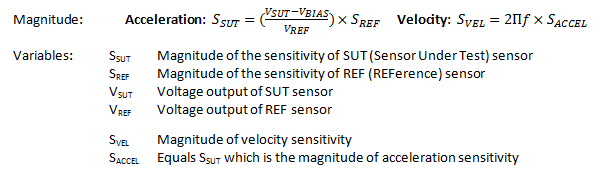
The operation of 4-20 mA current loop vibration sensors is quite different from a typical ICP® or charge type of vibration transducer. ICP sensors operate with a DC constant current power source and a dynamic AC voltage output signal proportional to the motion applied to the sensor. In turn, 4-20 mA current loop vibration sensors operate with a DC constant voltage source and produce a DC current proportional to the motion applied. Because of the differences in power and output signal type, as well as the output range of the 4-20 mA current loop vibration sensor, additional considerations apply in order to properly calibrate these types of sensors.
Because most data acquisition systems measure voltage instead of current, a precision shunt resistor is placed in the circuit for the purpose of making an accurate voltage measurement. The schematic in Figure 1 shows the typical circuit layout for calibrating 4-20mA current loop vibration sensors.
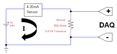
Figure 1
Using a 24 VDC power supply as the voltage source, the shunt resistor is placed on the signal side of the circuit in parallel with the data acquisition. Because the measurement is based on a current output, the presence of the shunt resistor in the circuit does not change the output of the sensor. The shunt resistor, which is a precision 500 Ohm ±0.01% resistor, causes a voltage drop as loop current flows through the resistor. The resistor itself must first be calibrated by simply making a resistance measurement using a calibrated DMM. Once the resistance value is known, apply Ohm’s Law, V= I×R or I=V⁄R, to the voltage measured by the DAQ and the output of the transducer can be accurately calculated.
Now that the method to make a precise current measurement for a 4-20 mA current loop vibration sensor is known, there is one more step required before calculating the sensitivity and performing a frequency sweep. The 4-20 mA current loop vibration sensor operation relies on a “live” ground. This is the zero motion output of the sensor, which is ideally at 4 mA. To accurately calculate the transducer sensitivity, the zero motion bias must be removed from the measurement. With the precision resistor value known, and the bias voltage measured, the following formulas are then applied to calculate the sensitivity at each frequency of the 4-20mA current loop vibration sensor in acceleration or velocity (depending on sensor type).