Main Menu
- Home
- Product Finder
- Calibration Systems
- Calibration Services
- Digital Sensing
- Industrial Vibration Calibration
- Modal and Vibration Testing
- Non-Destructive Testing
- Sound & Vibration Rental Program
- Learn
- About Us
- Contact Us
Vibration calibration methodologies are defined in various sections of ISO 16063. Within this standard, the measurement of accelerometer frequency response calibration can be performed using either primary or secondary means, as stated by ISO 16063 Part 11 (1999) and Part 21 (2003) respectively. Primary accelerometer calibration utilizes a laser interferometer as reference. Secondary calibration techniques use a transfer standard, typically another accelerometer, to calibrate the accelerometer under test and provide traceability to a primary standard.
These transfer standards are generally available in two different package designs. The first, and most common, is a double-ended accelerometer, often called a “piggy-back” reference accelerometer (Figure 1). It is designed specifically to carry another Sensor Under Test (SUT) to perform this secondary transfer calibration. These types of reference accelerometers are threaded on both the top and bottom sides of the unit, so that the base of the double sided transfer standard can mount directly onto a shaker and a SUT can mount directly to its top. The top surface of these piggy-back accelerometers is the calibrated mating surface, preferably calibrated directly against a laser interferometer to provide traceability with the best measurement uncertainty. The bottom portion of the double-ended reference accelerometer design is solid, providing a relatively large, massive base for the unit when mounted properly. It should never be mounted “upside-down” as this mounting configuration has dramatically different boundary conditions compared to “upside-up” mounting as the unit itself is calibrated. The net result is significant frequency response calibration errors in the mid-to-high frequency range, shown below for one of the more common double-ended reference accelerometers commercially available.
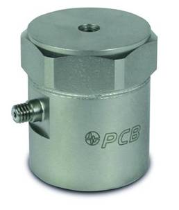
Figure 1. PCB Piezotronics Model 301A10 double-ended transfer standard reference accelerometer
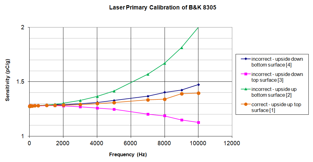
Figure 2. Laser primary calibration data for multiple test configurations of B&K 8305

Table 1. Test configurations for calibrating a double-ended transfer standard reference accelerometer
The data displayed here was acquired using The Modal Shop’s ISO 17025 accredited laser primary accelerometer calibration system. The B&K 8305 reference accelerometer was mounted on an air bearing shaker in both upside-up and upside-down configurations as described in the table above. The plot shows the corresponding calibration frequency response data acquired against the laser reference for these four test configurations. Figure 3 shows the two mounting configurations each with two possible laser reference measurement locations. Correct calibration results are obtained by mounting the double-ended reference accelerometer upside-up, with the laser reference measurement made on the upper exposed SUT mounting surface, indicated by the Orange #1. Since the reference accelerometer is calibrated this way, it should always be used exactly this way. All other calibration configurations generate significant bias errors, especially at higher frequencies, as shown by Figure 2 and detailed in Table 1.
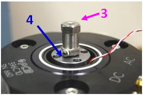
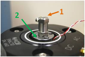
Figure 3. Test configurations for laser calibration of B&K 8305
The second type of transfer standard package design is a single-ended standard. These reference accelerometers are designed specifically to mount on top of the piggy-back reference accelerometer like any other SUT, as shown in Figure 4, to properly calibrate double-ended reference accelerometers that are not calibrated directly against a laser. The single-ended design provides a smooth frequency response function over a very wide frequency range, providing the ability to properly calibrate the frequency response of the more common piggy-back references up to 20 kHz, dependent upon the specifications of the model chosen. It is strongly recommended to calibrate single-ended transfer standards directly against a laser primary since their sole purpose is to calibrate double-ended reference accelerometers for use as a working transfer standard. If this unit is not directly calibrated against a laser, the level of measurement uncertainty will become exceedingly high with too many links between it and the primary laser reference.
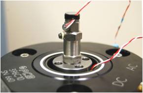
Figure 4. Single-ended transfer standard Model 9105C11 mounted atop Model 8305 double-ended transfer standard
Double-ended transfer standard accelerometers are available from many accelerometer manufacturers (Figure 5) and are certainly much more common than single-ended transfer standards. Bruel & Kjaer offers the 8305 reference accelerometer, and Endevco the 2270 reference accelerometer, both traditional charge mode designs. PCB Piezotronics offers the 301A10 reference accelerometer, a stable, high sensitivity quartz ICP® design (above, Figure 1). The Modal Shop offers single-ended reference accelerometer kits, such as the 9105C11, shown in Figure 4 calibrating a B&K 8305 double-ended reference accelerometer mounted properly on an air bearing shaker. Other manufacturers also offer single-ended transfer standards, such as the B&K 8305-001 and Endevco 2270M8, for performing less common transfer standard calibrations on working standard reference accelerometers and handheld or portable vibration calibrators. It is critical to use the proper type of transfer standard mounted in its correct configuration to obtain accurate calibration results.
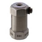
Figure 5. Common double-ended transfer standard reference accelerometers