Main Menu
- Home
- Product Finder
- Calibration Systems
- Calibration Services
- Digital Sensing
- Industrial Vibration Calibration
- Modal and Vibration Testing
- Non-Destructive Testing
- Sound & Vibration Rental Program
- Learn
- About Us
- Contact Us
We often get asked the question, “How do I mount a triaxial accelerometer to calibrate the (in plane) X and Y axes, when there is only a single Z axis mounting hole?” Clearly the Z axis stud mount poses no problems, but questions follow such as, “Can I adhesively mount it on the cap or case?” or “Why can’t I get my accelerometer to pass in the off axes direction?” Our answer is always the engineering favorite, “Well… it depends.” Lets take a look at the problems in a little more detail…
As we said above, the Z axis is usually no problem. It is afforded the “luxury” of an ideal mount with included stud mounting or rigid flat mounting base. Often, a second axis could be adhesively mounted. The most trouble comes when trying to calibrate the third axis that lines up with the electrical connector. In these cases here are our suggestions:
First – Ask your vendor how they do it in production calibration. They are good at getting a flat response (and keeping their yield up). Sometimes the vendor will have a special mounting bracket to hold the sensor properly rotated for the X or Y axes to match the direction of the excitation motion and acceleration reference accelerometer and to correctly align the center of the sensing element with the reference center. If the vendor has special mounting hardware, ask them to provide the bracket or a technical drawing. Duplicating their mount is key in reproducing “ideal sensor behavior”.
Second – If the vendor information is not available (or they advise that they glue the accelerometer) then an adhesive bond is the next choice, but be careful! At all cost, avoid bonding to the round welded “cap” that covers and seals the accelerometer sensing element. In this case, you will fail the high frequency calibration as the sensor “bounces” on a mode of the cap. In the worst case, if your accelerometer has a simple bonded cover (rather than welded) you may actually damage the accelerometer by tearing off the cap during the removal process. For the best broad frequency flat line response for integral triaxial accelerometers, we have had good experience mounting the accelerometer with X or Y axes cap down by placing very small amounts of super glue in only the structural corners of the triaxial accelerometer (facing the cap down but avoiding any bond to the cap itself).
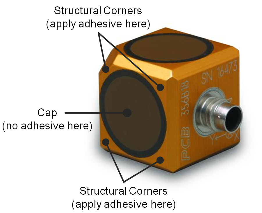
Figure 1: Triaxial Accelerometer.
Now that we have discussed creating an ideal mount, this brings about another question, “How do I know the performance of my accelerometer on ANY given mount?”
 If you are lucky enough
to have your own calibration system with calibration shaker and reference accelerometer, simply mount your Sensor Under Test (SUT) and run a calibration sweep. However, if you don’t have access to your own calibration system, there is still
a simple alternative to characterize accelerometer mounting. The technique called Structural Gravimetric Calibration turns out to be a simple and versatile means of using inexpensive tools you may already have at hand for validating any accelerometer
and mount. The basic tools needed are: a dynamic force sensor, a rigid mass, your SUT accelerometer, a support rig like the one shown on the right, manual excitation and an FFT analyzer. By mounting your SUT accelerometer on the rigid mass via your
chosen mounting method (i.e. bees wax), the rig can provide easy validation of the usable frequency range of a given sensor mounting method.
If you are lucky enough
to have your own calibration system with calibration shaker and reference accelerometer, simply mount your Sensor Under Test (SUT) and run a calibration sweep. However, if you don’t have access to your own calibration system, there is still
a simple alternative to characterize accelerometer mounting. The technique called Structural Gravimetric Calibration turns out to be a simple and versatile means of using inexpensive tools you may already have at hand for validating any accelerometer
and mount. The basic tools needed are: a dynamic force sensor, a rigid mass, your SUT accelerometer, a support rig like the one shown on the right, manual excitation and an FFT analyzer. By mounting your SUT accelerometer on the rigid mass via your
chosen mounting method (i.e. bees wax), the rig can provide easy validation of the usable frequency range of a given sensor mounting method.
The Structural Gravimetric Calibrator Rig functions to transfer known or measured motion caused by gravity and other forces into electrical signals for comparison purposes. Operation relies on the rigid test masses obeying Newton’s Laws of Motion, and upon the unusual behavior of a taut monofilament line. Striking the top end (junction) of the line causes it to buckle, allowing the test object to experience a 1 “G” step input for a short period of free fall. Coupled to a 2-channel analyzer, this clever setup delivers both step and impulsive functions from free fall drop, broad band low/medium frequency, as well as hammer calibrations.
For single point sensitivity, accelerometers and load cells may be “drop” calibrated without a reference sensor; instead, Earth’s gravity is used as a reference. Accelerometers are mounted to a mass suspended on a taut line. The junction is tapped, the accelerometer undergoes free fall (a step function of 1 g), and the sensitivity is calculated directly from the measured voltage step function and gravity. Similarly, force sensors are loaded by suspending a calibrated mass on a taut line. The junction is tapped, and the sensitivity is calculated from the measured voltage step and the weight of the known mass.
Gravimetric comparison calibration of accelerometers and force measuring impact hammers are accomplished by evaluating the transfer function of a rigid body mass. A reference sensor is attached to one end of the mass with the test sensor on the other end. By exciting (either manually or by electro-dynamic shaker) the instrumented mass and measuring the transfer function (A/F) the result should yield a flat line equal to 1/M over the frequency range, shown below. Any deviation in magnitude or phase from the expected flat line transfer behavior represents the characteristics for the test sensor and its mounting.
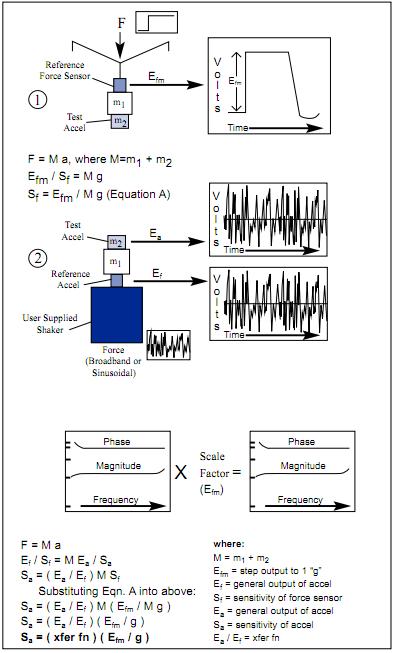
Figure 2: Accelerometer Structural Gravimetric Calibration.
In the end, this technique easily allows you to characterize any mount from mounting clay or putty, to hot melt glue, to cyanoacrylate “super” glue. Give it a try… and give us a shout if you have any questions about either the technique or the behavior of your sensors.