Main Menu
- Home
- Product Finder
- Calibration Systems
- Calibration Services
- Digital Sensing
- Industrial Vibration Calibration
- Modal and Vibration Testing
- Non-Destructive Testing
- Sound & Vibration Rental Program
- Learn
- About Us
- Contact Us
 Eddy current probes, or proximity
probes, are non-contact displacement sensors that protect some of the world’s most critical rotating equipment, like gas and steam turbines, from catastrophic failure related to excess vibration. By measuring the distance between probe tip and
shaft, using changes in the magnetic field, users can effectively plot the motion of the shaft and determine if fault conditions exist such as imbalance and misalignment. Keeping turbines running and properly scheduling maintenance during planned
outages is paramount to the success of the plant.
Eddy current probes, or proximity
probes, are non-contact displacement sensors that protect some of the world’s most critical rotating equipment, like gas and steam turbines, from catastrophic failure related to excess vibration. By measuring the distance between probe tip and
shaft, using changes in the magnetic field, users can effectively plot the motion of the shaft and determine if fault conditions exist such as imbalance and misalignment. Keeping turbines running and properly scheduling maintenance during planned
outages is paramount to the success of the plant.
The probe system consists of the probe itself with typical 5-, 8- or 11-mm encapsulated probe tip, an extension cable and a probe driver or signal conditioner. The probe impedance changes proportional to distance from the shaft or target, however, probe impedance alone is not linear. It is the job of the probe driver to linearize these impedance changes and produce a reliable voltage signal relating distance to voltage. Since impedance is critical to this measurement, cable length and type must be precisely matched to the probe driver.
Unfortunately, Eddy current probe cable installation error is one of the top reasons for failure of the vibration protection system. Making matters worse, this mistake can go undetected with a simple gap voltage check, causing catastrophic results.
A gap voltage check is a measure of the DC voltage output by the probe driver. It is easy to check since most monitoring systems have a gap voltage button on the front panel. When installing an Eddy current probe during a shutdown, the technician wants to install the probe so that the initial distance or “gap” from the turbine shaft is close to the center of the probe’s dynamic range. Most probes have a range of 10 mils to 90 mils, thus the installer wants the initial gap to be as close to 50 mils as possible. This ensures the probe can be used to its maximum dynamic range since the shaft could, theoretically, travel 80 mils peak-to-peak and still be measured by the probe. However, if the shaft is moving 80 mils peak-to-peak it is probably better to evacuate the premises rather than stick around and watch what happens. Most radial probe alarms are set at less than 10 mils peak-to-peak. Thus, from a practical standpoint, the initial gap can vary from 40 mils to 60 mils and, as long as the proper cabling is used, the probe will measure correctly.
A cabling error of just 0.5 meters can cause significant error of 12.5%. For example, a system designed for 5 meters of cable and 200 mV/mil output when connected with 5.5 meters of cable produces 175 mV/mil. With the monitoring system expecting 200 mV/mil, an alarm at 5 mils will not trip until there is actually 5.7 mils vibration.
Gap voltage can be used to detect cable error, but most often inadvertently leads to more inaccuracy. Usually, it is impossible to visually observe or measure the actual probe tip distance from the shaft. So if the gap voltage is wrong, how can one tell if it is caused by cable error or installation error? If the technician cannot physically measure the distance from probe tip to shaft during a turbine shut down, it is impossible to know for sure. The easy fix is to adjust the position of the probe to make the gap voltage look correct. By doing so, the probe tip (with incorrect cable length attached) is being positioned so that the turbine shaft is no longer in the center of its dynamic range. This leads to additional dynamic output error. In our 5.5 meter example, dynamic voltage drops to 168 mV/mil. If an alarm was supposed to be at 5 mils, it will not trip until there is actually 6 mils vibration.
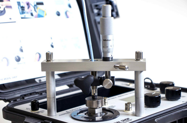
Dynamic calibration against the API 670 recommended 4140 steel target is the best way to identify cable error. Using a known displacement input, the technician can measure the dynamic AC voltage output of the Eddy current probe and confirm that it is 200 mV/mil. The Modal Shop's Model 9100D allows customers to perform this dynamic validation with displacement in mils or microns peak-to-peak on an LCD display. Model 9110D offers the same capability plus sensitivity display and the ability to create ISO 17025-compliant calibration certificates for both amplitude linearity and frequency response.