Main Menu
- Home
- Product Finder
- Calibration Systems
- Calibration Services
- Digital Sensing
- Industrial Vibration Calibration
- Modal and Vibration Testing
- Non-Destructive Testing
- Sound & Vibration Rental Program
- Learn
- About Us
- Contact Us
 When seeking the best uncertainties and most consistent daily verification and operation of your accelerometer calibration system, it pays to know your sensor details. The key to accelerometer calibration is ensuring that everything starts from a “flat line." This means no relative motion between Reference Accelerometer and Sensor-Under-Test, as well as no local resonances and strain effects from connectors and cables.
The practical keys to this are the attention to structural details. Pay attention to:
By understanding structures you can construct and operate an accelerometer calibration system that avoids resonant modes which cause amplified or relative motion.
The first key is the rigidity and uniaxial performance of the shaker and accelerometer reference. The shaker/reference combination must be rigid to extremely high frequencies and design constrained to nearly pure uniaxial motion. This includes minimizing both the cross axis motion sensed by the reference and cross axis motion induced by the exciter. We have covered this topic a number of times in the past relating to the necessity of a proven design of a modern precision calibration grade air-bearing exciter. Please click here to past articles if you need a refresher.
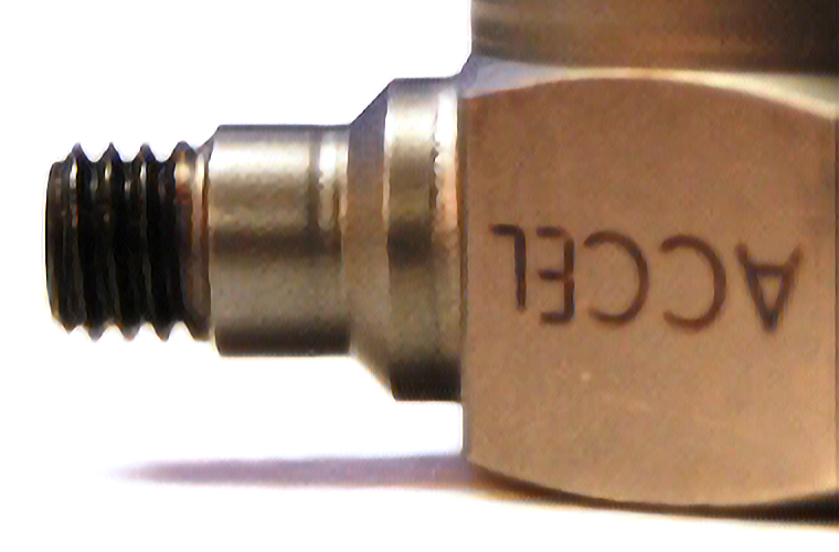
The combination of the second and third keys ensures the flattest response to the system and daily verification accelerometer providing the best daily performance and uncertainties. While at first, it may seem that a top connector daily reference would be preferred for its inherent symmetry about the exciter line of action, we recommend a side connector daily validation transducer. First, since the side connector will be non-symmetric about the exciter line of action, we select a model with a short connector anchored into the structurally rigid accelerometer base, thereby raising the mechanical resonance of the connector itself. Second, the side exit connector allows us to secure (to the nearest shaker body location) a minimal length of strain relieved signal cable. This minimized strain relief loop provides the flattest and most consistent output from the accelerometer. In addition to operator skill and sound daily practices, this consistency enhancing technique is especially important when gathering sample data for important calculations like uncertainties.
Note: In cases of absolute best uncertainties (like The Modal Shop's “gold standard” reference in house which is shuttled to NIST or PTB and proficiency tested against PCB Piezotronics), we choose an accelerometer with no connector at all. Selecting a design with solder tab connection removes virtually all of the connector mass. The functional price of this is, however, reduced cable junction life. Accordingly, it is not used on the daily verification sensor, but rather on the sparingly used gold standard accelerometer.
Like many measurement processes, there are always competing tradeoffs to be decided upon depending on your primary and secondary goals. If you have questions, please don’t hesitate to contact us directly. We are here to answer your accelerometer and calibration questions.