Main Menu
- Home
- Product Finder
- Calibration Systems
- Calibration Services
- Digital Sensing
- Industrial Vibration Calibration
- Modal and Vibration Testing
- Non-Destructive Testing
- Sound & Vibration Rental Program
- Learn
- About Us
- Contact Us
One of the original sound and vibration test instruments is the variable gain charge amplifier. Charge amplifiers convert a high impedance signal from a piezoelectric sensor to low impedance voltage signals. These low impedance signals are suitable for input to a data acquisition system or oscilloscope. Charge amplifiers are still used in applications that exceed the temperature specifications of an ICP® sensor. Another application for charge amplifiers is calibration systems like the Vibration Calibration Workstation Model 9155D from The Modal Shop. In this case, the 9155D software automatically switches the amplifier between ICP and charge mode.
In addition, the software also optimizes the somewhat complex gain settings of the charge amplifier. This article describes how to adjust these settings for situations where software is not used.
When data acquisition software is available with calibration corrections, choosing the gain of a signal conditioner is simple. Let’s consider this example measurement chain:
Charge mode accelerometer, sensitivity = 0.019 pC/ms-2
Data acquisition system full scale input range = 1 Volt
Expected maximum acceleration = 5000 ms-2
Suppose also we want to match the full scale acceleration to the full scale input voltage of the data acquisition system (this maximizes the resolution of low-level signals):
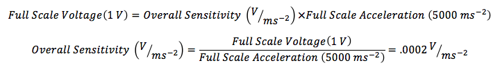
This relates to a charge amplifier gain and sensor sensitivity:
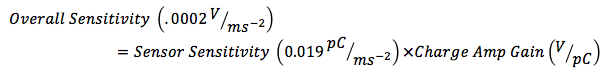
We use this to find the required gain of the charge amplifier:
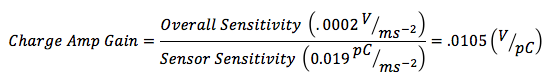
...or approximately 10 mV/pC. At this point, we can easily select a PCB Model 422E02 with a calibrated fixed gain of, for example, 9.98 mV/pC. Now we can calculate the overall sensitivity of the channel with these calibrated, rather than nominal, values:

...and then enter 0.197 mV/ms-2 into our data acquisition system software for the calibration value of the channel. The software adjusts accordingly.
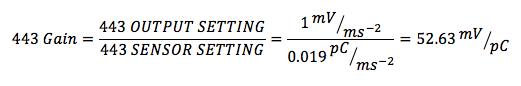
But there is another situation where data acquisition software is not available, but an accurate voltage measurement is. In this case, it is more convenient to set the charge amplifier gain such that, for example, 1 mV = 1 ms-2, (or an overall sensitivity of 1 mV/ms-2), exactly. We calculate this below:
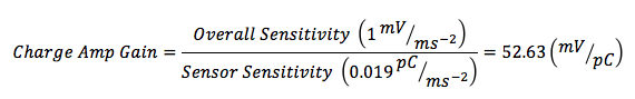
It is unlikely to randomly find a charge amplifier with a calibrated gain of exactly 52.63 mV/pC. This is where the 443B101 offers a convenient solution. The 443B101 controls overall gain with two settings: Output, or Output Sensitivity, and Sensor, or Transducer Sensitivity.
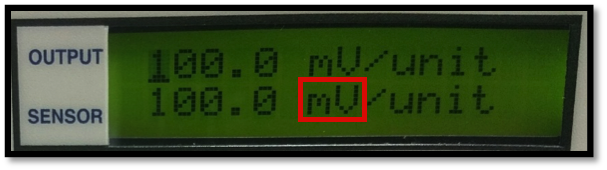
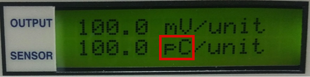
Both of these settings are adjusted from the front panel. The overall gain of the 443B101 is the output setting divided by the sensor setting:
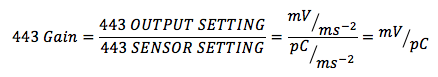
The output can be quickly scaled to 1 mV/ms-2 with the following settings:
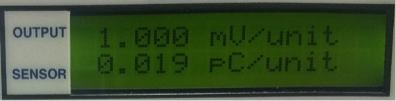
To confirm, we can calculate the overall gain of the 443B101:
...which compares favorably to the previous calculation. Not only does a signal conditioner like the 443B101 offer the precision gain and accuracy for sensor calibration, it provides the advantage of quickly adjusting gain so that voltage output = engineering units–whether it be ms-2, g, psi, bar, Pa, or any other unit.