Main Menu
- Home
- Product Finder
- Calibration Systems
- Calibration Services
- Digital Sensing
- Industrial Vibration Calibration
- Modal and Vibration Testing
- Non-Destructive Testing
- Sound & Vibration Rental Program
- Learn
- About Us
- Contact Us
In last month’s article, we learned how to measure the open circuit sensitivity of a precision condenser microphone using the insert voltage technique. This month, we will talk about how to measure the frequency response curve of a precision condenser microphone using the electrostatic actuator method as outlined in the International Electrotechnical Commission (IEC) section 61094-6.
Before delving into the “whats” and “hows” of electrostatic actuator calibration, let us first talk about why the electrostatic actuator method is the preferred method of measuring the frequency response of precision condenser microphones. There are three types of ideal sound fields: the pressure field, the free field and the random incidence or diffuse field. In a pressure field, the microphone is part of the sound field and the sound pressure waves are passing directly over the diaphragm of the microphone. In a free field, there is a single sound source and the microphone is pointed directly at it. Finally, a diffuse field can have multiple sound sources that can be at any angle relative to the microphone diaphragm.
In order to create any of the three ideal sound fields, precision fixtures and an anechoic chamber are required along with specific technical expertise and understanding of acoustics. Because of the high level of technical knowledge required, combined with the cost and immobility of anechoic chambers, performing precision condenser microphone frequency response calibrations in the ideal sound fields is not feasible or efficient for most applications. Performing a frequency response calibration using the electrostatic actuator technique is not only portable and relatively low-cost, but it also removes the need for highly specialized technical expertise.
The basis of the electrostatic actuator method is in the way that the actuator excites the diaphragm of the microphone being tested. A voltage is applied across the actuator, creating an electrostatic force which then drives a sound pressure across the diaphragm of the precision condenser microphone. In order to create a constant electrostatic force across the desired frequency range, an AC voltage of constant amplitude and varying frequency is applied across the electrostatic actuator along with a DC voltage. Figure 1 below (taken directly from Annex B of IEC 61094-6) demonstrates the typical set-up for performing an electrostatic actuator frequency response calibration.
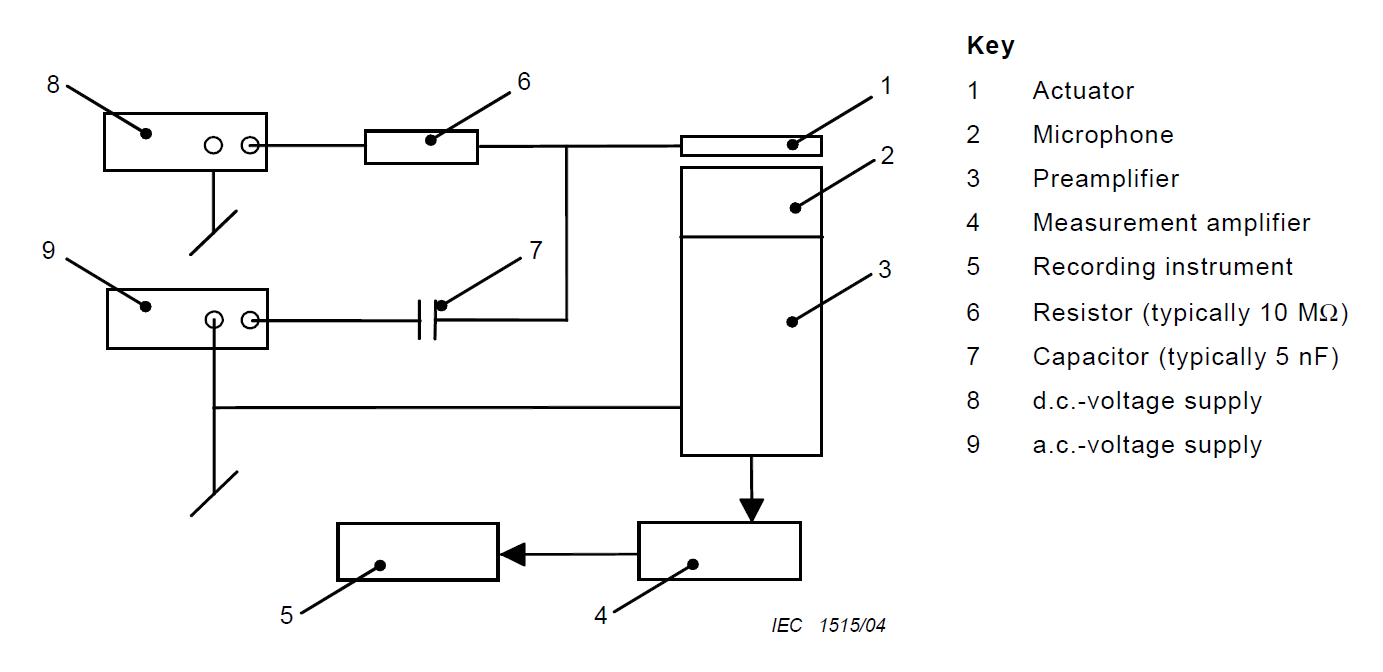
Figure 1: Typical Electrostatic Actuator Frequency Response Test Set-Up
The typical voltage levels are 800 VDC and 30 VAC. With a constant 30 VAC applied across the electrostatic actuator at every frequency point of interest, the electrostatic actuator will produce a pressure of about 1 Pa (Pascal). Depending on the sensitivity of the microphone being tested, 1 Pa can result in a very low voltage output from the microphone, which can be susceptible to cross-talk between the electrostatic actuator signal and the microphone signal. To minimize the potential effects of cross-talk, a higher amplitude AC voltage can be applied across the electrostatic actuator.
The electrostatic actuator method provides a response very similar to the pressure field response of the microphone being tested. The electrostatic actuator response is so similar to the pressure field response that most precision condenser microphone manufacturers do not publish a correction factor for pressure field microphones. For free-field and diffuse-field microphones, microphone manufacturers typically publish correction factors for each specific precision condenser microphone model. Because the unit of acoustic measurements is dB (decibels), the correction factors can simply be added to the measured response to convert the electrostatic actuator response to that of the desired field for the microphone being tested. Like vibration transducers, the frequency response curve for precision condenser microphones is usually plotted in reference to the sensitivity of the microphone at the reference frequency. Figure 2 shows a typical response with correction for a free-field microphone.
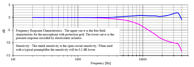
Figure 2: Example of Free Field Response with Correction Curve
Notice that the electrostatic actuator frequency response in Figure 2 starts at 200 Hz. While the electrostatic actuator is capable of creating an electrostatic force at lower frequencies, it is typically not recommended to go lower than 100 Hz or 200 Hz. The low frequency response of the electrostatic actuator is not a function of the electrostatic actuator, but rather of the microphone itself. All precision condenser microphones have a vent (either side or rear) which allows the pressure on the inside of the microphone to stay the same as the pressure outside of the microphone. When in a sound field, the sound pressure excites both the diaphragm and the vent, allowing the microphone to have an accurate response to low frequencies. When driving the microphone using the electrostatic actuator, however, only the diaphragm is being excited. There is no sound field to excite the vent at the same time as the diaphragm which causes error in the measurement at lower frequencies.
Making accurate calibration measurements for precision condenser microphones may seem challenging, however, using the processes outlined in this two-part article can make the calibration relatively simple to perform without the need for highly specialized acoustic knowledge. Using the Insert Voltage Technique to get the microphone sensitivity and the Electrostatic Actuator Method to get the frequency response gives all of the information necessary to quickly create an accurate calibration certificate for the microphone under test.