Main Menu
- Home
- Product Finder
- Calibration Systems
- Calibration Services
- Digital Sensing
- Industrial Vibration Calibration
- Modal and Vibration Testing
- Non-Destructive Testing
- Sound & Vibration Rental Program
- Learn
- About Us
- Contact Us
While most sound and vibration measurement professionals are familiar with the sweeping implications of ISO 9000, many users are not aware of the level of detail available in ISO 16063. The ISO 16063 standard governs the methods for the calibration of vibration and shock transducers.
Part 1 of the standard covers the basic concepts and the overview of methods for the calibration of vibration and shock transducers. Essentially, this standard covers the major performance/behavior characteristics of a vibration transducer and breaks them into two major classifications: direct response and spurious response.
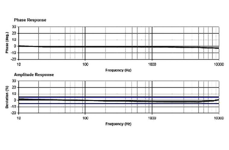
Direct response is the transducer’s output to the primary input or measurand. The sensing element of a vibration transducer is designed to measure the translational acceleration in a single direction. (Triaxial accelerometers have three separate sensing elements to measure the acceleration in three orthogonal directions – essentially three individual sensors in one convenient package.) Its direct response is the frequency response output of the transducer due to a mechanical vibration input aligned with its sensing axis. Ideally, this includes testing for a flat frequency response in both magnitude and phase, as well as straight-line linearity over a given range of amplitude inputs. In fact, the continued validation of this frequency response for magnitude and phase is the fundamental output of the regular calibration of your accelerometers.
A spurious response is the output of the transducer to any varying input other than that which is the input for the direct response – in this case the mechanical vibration aligned with its primary sensing axis. This includes the following: temperature dependency, transient temperature sensitivity, transverse vibration sensitivity, rotational vibration sensitivity, strain sensitivity, magnetic sensitivity, sensitivity to mounting torque, etc. Ideally, the transducer is designed to reduce or eliminate its spurious output in the users’ measurements. Typically, manufacturers validate the sensor design by testing the transducer’s sensitivities to these spurious inputs during R&D and initial production. Therefore, many of these tests are not governed by standardized testing methodologies. Of the various spurious responses, transverse vibration sensitivity (often called cross-axis sensitivity) is one that users occasionally wish to test on their own. For this reason, commercially available transverse calibration systems exist, as well as a standard (16063-31) covering it.
The final section of Part 1 of the 16063 standard covers the expression of uncertainties. The area of uncertainties is probably the most intensive and most debated area of accelerometer calibration. Besides being driven by human nature
issues (like national pride among labs), the area of uncertainties continues to evolve as the dynamics of acceleration sensing and the calibration measurement process are better understood and advances are made in technology. Current state of
the art in primary calibration has measurement uncertainties around 0.2% to 1.5% depending upon frequency range. Measurement uncertainties for typical secondary calibration are around 1% to 3% for comparison calibration systems.
| Published Uncertainty | ||||
|---|---|---|---|---|
| 10 Hz to 99 Hz | 100 Hz | 101 Hz to 920 Hz | 921 Hz to 5000 Hz | 5001 Hz to 10,000 Hz |
| 0.90 % | 0.85 % | 0.90 % | 1.25 % | 1.70 % |
Sample Expanded Uncertainty Table
The bulk of the remaining parts of the 16063 standard describe in detail various primary and secondary methodologies of calibrating a transducer’s frequency response, or its direct response as described previously. A back-to-back comparison method is the most common way of accomplishing this accelerometer calibration, covered under 16063-21. This calibration technique is generally used by transducer manufacturers on their production lines, as well as by metrology labs providing recalibration services. Less common but higher accuracy primary methods include laser interferometry (covered under 16063-11) and reciprocity (covered under 16063-12). Given a substantial price difference between commercially available laser primary calibration systems and back-to-back comparison calibration systems, the use of the higher accuracy primary calibration methods is generally limited to national metrology labs and some of the transducer manufacturers.
In the coming months, we’ll start to investigate the details of the most common methods of standardized calibration. The table below provides an easy reference on the component parts of the standard.
16063 standard for calibrating shock and vibration standards
- a. –11 primary vibration calibration by laser interferometry
- b. –12 primary vibration calibration by reciprocity
- c. –13 primary shock calibration by laser interferometry
- d. –15 angular vibration calibration by laser interferometry
- e. –21 vibration calibration by comparison
- f. –22 shock calibration by comparison to a reference
- g. –31 testing of transverse sensitivity
- h. –41 calibration of laser vibrometers