Main Menu
- Home
- Product Finder
- Calibration Systems
- Calibration Services
- Digital Sensing
- Industrial Vibration Calibration
- Modal and Vibration Testing
- Non-Destructive Testing
- Sound & Vibration Rental Program
- Learn
- About Us
- Contact Us
The game of American football is sometimes called a “game of inches.” Just as an inch of extra forward progress can determine the outcome of an individual play, an inch (or centimeter) can also determine the quality of your calibration at low frequency. As a rule of thumb, in the low frequency range there is no substitute for a longer stroke exciter. Consider that “normal” calibrations for a 100 mV/g accelerometer are conducted at a constant 1 g acceleration level. This one g constant acceleration is held fixed to the maximum frequency in the range of calibration.
However, at lower frequencies, simple displacement calculations show us that the 1 g excitation level is unobtainable on a conventional 10 mm stroke broad frequency range (5 Hz to 15 kHz) calibration exciter. By the time the calibration frequency falls to 7.65 Hz, an 8.5 mm stroke (which is 85% of the exciter’s absolute maximum 10 mm stroke against stops) generates 1 g. Below this frequency, say at 5 Hz and 2 Hz the calibration exciter would need a stroke of 19.9 mm and 125 mm accordingly to keep the reference acceleration level at 1 g. The practical outcome of this problem of limited shaker stroke is that constant acceleration accelerometer calibrations are only achievable down to a cut off frequency (about 24 Hz for 10 g and 7.65 Hz for 1 g, both on the 8.5 mm stroke) where the shaker stroke is maxed out and the acceleration then becomes a declining function for any lower frequencies (see Plot 1).
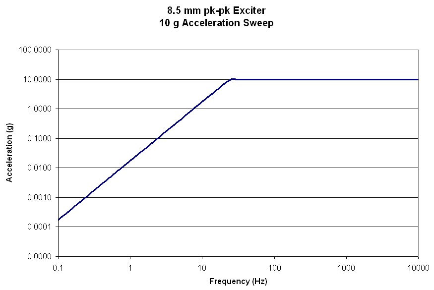
Plot 1 – Acceleration limitation over frequency for an 8.5 mm constant displacement
It logically follows that at declining acceleration levels, the output of both the calibration reference accelerometer (typically 10 mV/g reference accelerometer for general purpose calibration) and sensor under test (SUT) also output lower and lower signal levels as the calibration frequency falls. This becomes most challenging as the calibration frequency falls through the declining 5 to 2 Hz range with the signal levels of a general purpose 10 mV/g reference accelerometer approaching its noise floor on an 8.5 mm stroke calibration exciter. While signal averaging can improve measurement coherence and uncertainties at the expense of cycle time, most serious and regular low frequency calibration users opt for a long stroke exciter option to increase the exciter displacement and resulting signal levels of the accelerometers.
A new adaptation of linear motor technology creates a low frequency long stroke exciter with longer displacements and minimal distortion and errors at the critical low frequency calibration range. Consider the new standard of a 250 mm long stroke precision calibration exciter and the benefit for low frequency calibration for a user of lightweight 100 mv/g accelerometers, such as those used on a large flexible space structure measuring down to 0.5 Hz. It is important to remember that one characteristic of typical piezoelectric accelerometer output is a rising noise floor proportional to one over frequency (1/f) due to internal circuit noise dominated by resistor noise. This functionally decreases the measurement resolution of the accelerometer in the range where the acceleration measured is the lowest. (See Plot 2)
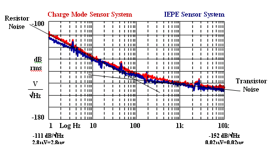
Plot 2 – Linear approximation ranges for Charge and IEPE equivalent accelerometer spectral noise floor
This rising noise floor is the genesis for the implementation of longer stroke excitation (and often a higher sensitivity, 500 mV/g, higher resolution reference accelerometer) into low frequency calibration system designs. By implementing a 250 mm stroke precision calibration exciter, the acceleration levels achievable at lower frequencies remain above the rising noise floor of both the SUT and the reference accelerometer. In Plot 3, the approximated noise floor for both a 10 mV/g and 100 mV/g accelerometer are plotted with a dotted line, representing a level two orders of magnitude above the actual noise floor. The guideline of an excitation level two orders of magnitude above the lowest of the SUT and/or reference accelerometer ensures both best uncertainties and minimizes calibration cycle time by reducing the need for averaging. With this excitation headroom, Plot 3 shows that low uncertainty low frequency calibrations can be made to well below 0.3 Hz with a 250 mm stroke and a 100 mV/g SUT (effective resolution of 320 micro-g per root Hz at 1 Hz). By the same methodology, we can see that for the case of a 10 mV/g reference accelerometer on the 8.5 mm displacement curve the cross over with headroom occurs at about 3 Hz.
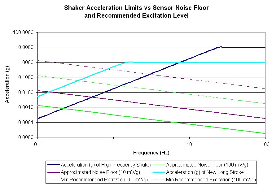
Plot 3 – 250 mm and 8.5 mm precision calibration exciter acceleration levels and accelerometer spectral noise for 100 mV/g and 10 mV/g
As the need to calibrate to even lower frequencies arises, such as geophones or other ultra low frequency velocity based transduction devices, this new excitation technology becomes even more valuable. The exciter length can be easily extended to extremely long lengths in excess of a meter or more. Additionally, the position feedback control of the design is accomplished via a novel (patent pending) optical encoder methodology which can serve as an ultra high resolution low frequency reference. This has the benefit of both maximizing useable displacement to 100% of stroke to stops and reduces the inherently long cycle time of low frequency calibration by eliminating the need for wasted control cycles.
Either way… Either reference… We are glad to help you with your low frequency calibration challenges. Just contact us - we’re here to serve you.