Main Menu
- Home
- Product Finder
- Calibration Systems
- Calibration Services
- Digital Sensing
- Industrial Vibration Calibration
- Modal and Vibration Testing
- Non-Destructive Testing
- Sound & Vibration Rental Program
- Learn
- About Us
- Contact Us
 Accelerometer users in the structural testing field often ask about how to calibrate a sensor’s performance at the low end of the frequency response curve. Since most manufacturers start the standard factory calibration at 10 Hz, there
is typically no data delivered with an accelerometer documenting its low frequency performance. To measure this data, a supplemental low frequency calibration must be performed.
Accelerometer users in the structural testing field often ask about how to calibrate a sensor’s performance at the low end of the frequency response curve. Since most manufacturers start the standard factory calibration at 10 Hz, there
is typically no data delivered with an accelerometer documenting its low frequency performance. To measure this data, a supplemental low frequency calibration must be performed.
In theory, low frequency calibration should be as simple as any other comparison (back-to-back) calibration, but practically speaking, there are always challenges. These are fundamentally related to the tradeoffs between sensitivity and frequency response. The challenge in low frequency calibration is typically not with the sensor under test (SUT) but rather with the reference accelerometer. In the world of PE accelerometer sensitivity, there is no substitution for seismic mass. A larger internal seismic mass provides more inertial force on the sensing crystal stack; and therefore, the design produces more output sensitivity. However, as more and more mass is added to a sensor design, the mounted resonant frequency is lowered and the upper end of the useable frequency range becomes lower and lower. This is why seismic accelerometers with sensitivities of 1 V/g or 10 V/g are typically the heaviest accelerometers and have the smallest range of flat frequency response. The limited upper frequency range of the seismic accelerometer is of little consequence since the typical area of application interest is normally below 50 Hertz. In the case of the calibration reference accelerometer, however, the designs often try to extend the frequency range at both ends to get the broadest response possible. Accordingly, to get a 10 kHz high end response, the seismic mass is typically smaller and the sensitivity may be only 10 mV/g. This limited sensitivity, coupled with the typical rising noise floor (proportional to 1/f) at low frequencies limits the practical low end calibration to about 5 Hz on 0.4 inch (1 cm) stroke calibration shaker. To extend the calibration frequency lower, the common method would be to implement an additional shaker of longer stroke to provide higher acceleration levels at the low frequencies (5 Hz down to a few tenths of a Hertz). For example, 0.4 inch stroke (pk-pk) at 1 Hz is 20 milli-g, while a 6 inch stroke (pk-pk) is 310 milli-g. Accelerometers are first calibrated on a standard calibration reference exciter, and then removed and remounted on the low frequency shaker/reference combined for a second calibration to verify the low range. Practically, this is less than ideal as it becomes a second complete hardware setup for low frequency calibration.
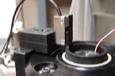
As a novel approach to tackling the challenges at these very low frequencies and small acceleration levels, there is now a new patent pending method using an optical encoder as the reference. The inherent benefit of employing a displacement based reference is that it has a flat noise floor (and resolution) regardless of frequency for a fixed displacement level. Now calibrations down to a few tenths of a hertz can be made quickly and with higher accuracy. The heart of the innovation centers around the use of a high resolution optical displacement encoder. The encoder and etched scale on tape pairing accurately measures displacement down to the tens of nanometer level. In terms of acceleration, this provides the functional equivalent of nano-g’s of resolution at 0.5 hz with only 0.4 inches of stroke. This is the functional equivalent of creating a reference accelerometer with over 10,000 V/g sensitivity! Of even more interest to the practical calibration laboratory, low frequency calibrations can now be done on the same shaker as general purpose calibrations. Learn more about low frequency calibration.