Main Menu
- Home
- Product Finder
- Calibration Systems
- Calibration Services
- Digital Sensing
- Industrial Vibration Calibration
- Modal and Vibration Testing
- Non-Destructive Testing
- Sound & Vibration Rental Program
- Learn
- About Us
- Contact Us
 Piezoelectric accelerometers are well suited for seismic vibrations studies. They are completely self contained and self generating from an inertial frame of reference. This eliminates the challenges with relative vibration found in optical/laser
methods, as well as dual ended attachment coil based methods, such as LVDTs. The second most common challenge with seismic measurements is the limited excitation levels of seismic events. In terms of acceleration, the g level falls
off exponentially for a constant displacement as frequency decreases, thus seismic events typically exhibit small acceleration levels.
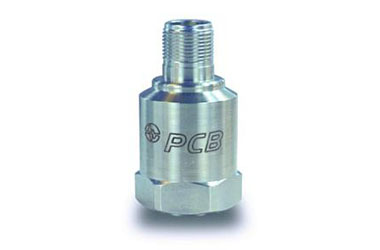
Piezoelectric accelerometers accommodate this measurement challenge through exceptionally high resolution created by their naturally high output (up to 10 V/g) and extremely low noise floor (typically sub-microvolt) with built-in ICP® impedance conversion electronics all hermetically sealed in a laser welded stainless steel sensor housing. This combination provides effective broadband resolutions on the order of one micro g and can still drive low impedance, noise immune signals. An additional benefit of ICP low output impedance transducers is the capability to drive long cable runs typically associated with seismic installations on bridges, buildings or other civil infrastructures. A final benefit of piezoelectric acceleration sensing is the solid state nature of the sensor construction. With no moving parts and the sealed stainless steel casing, the sensors are much more rugged/reliable when compared to servo or flexure based designs and can operate for long durations in outdoor conditions. For these reasons, it is common to find arrays of piezoelectric seismic accelerometers in applications ranging from civil infrastructure monitoring, to vibration limit switches to operating modal deflection shape measurement.
As far as challenges with piezoelectric seismic accelerometers, there are just a few points to consider. Foremost, remember that all piezoelectrics are AC coupled. Their low frequency response is governed by the discharge time constant (DTC) of the accelerometer (coupled with DTC of the measure/recording device). A typical seismic accelerometer may have a DTC of greater than 5 seconds which allows for a calibrated flat frequency response (-5%) down to 0.1 Hz. If true DC response is required, then the piezoelectric based measurement is abandoned for a DC responding based transduction method such as Variable Capacitance. Another important consideration to remember is the extremely high sensitivity of some seismic accelerometer and that even modest shock levels like the snapping attachment of a magnetic mount can generate 100’s of g’s and thereby 1000’s of volts of output which can damage the internal impedance conversion electronics. Finally, even for modest overloads such as gentle installations, the overload recovery time for the long time constant seismic accelerometers is measured in minutes. It is prudent to wait at least 5 minutes after installation and power up for the sensor bias signals to completely settle to a zero based level.
If you have additional questions or concerns with seismic sensing choices please ask your sensor vendor field application engineer or contact us directly. We’re always glad to help.