Main Menu
- Home
- Product Finder
- Calibration Systems
- Calibration Services
- Digital Sensing
- Industrial Vibration Calibration
- Modal and Vibration Testing
- Non-Destructive Testing
- Sound & Vibration Rental Program
- Learn
- About Us
- Contact Us
 Instrumentation & Controls technicians are the unsung
heroes of the industrial plant, charged with the daunting task of keeping the instrumentation that keeps everyone safe working and calibrated. It is a thankless, often overlooked, job. Calibration reports are critical to the team. Aside from ensuring
quality data and measurements, these reports help plants pass critical OSHA safety and insurance audits.
Instrumentation & Controls technicians are the unsung
heroes of the industrial plant, charged with the daunting task of keeping the instrumentation that keeps everyone safe working and calibrated. It is a thankless, often overlooked, job. Calibration reports are critical to the team. Aside from ensuring
quality data and measurements, these reports help plants pass critical OSHA safety and insurance audits.
The surge in popularity of the 4-20 mA vibration transmitters – which allow plants to monitor the health of critical pumps, motors and compressors using existing process control PLC or DCS systems – presents a new challenge to the I&C team:
How are 4-20 mA vibration transmitters calibrated? Actually, is “calibration” even the right term? For I&C technicians there is good news and bad news…
Regarding most 4-20 mA vibration transmitters, the bad news is they cannot be “trimmed” like traditional process instrumentation such as pressure or temperature sensors. Hence it is debatable whether calibration is even the right term. The sensor cannot be adjusted. The only way to “fix” a drifted output is to change the scaling in the PLC or DCS. Traditional “as found”, “as left” calibration notes do not apply.
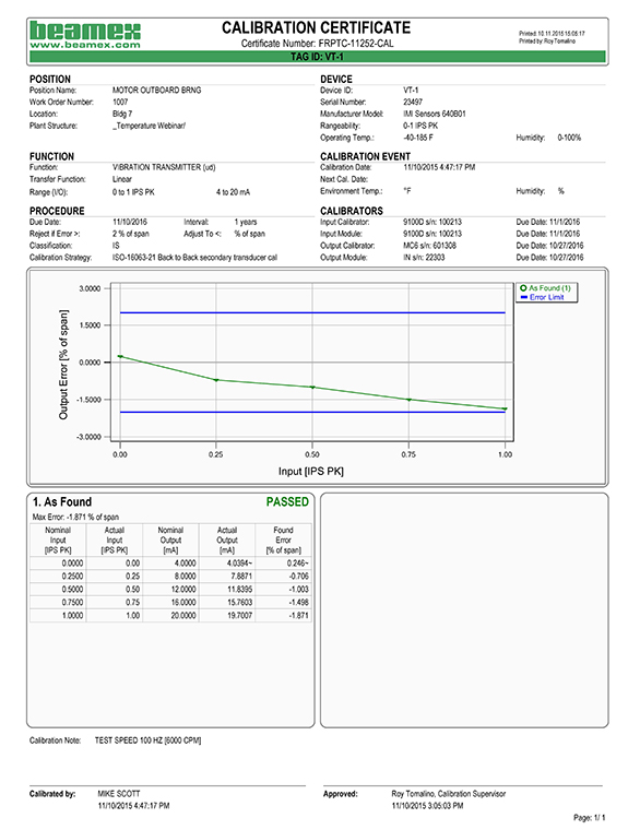
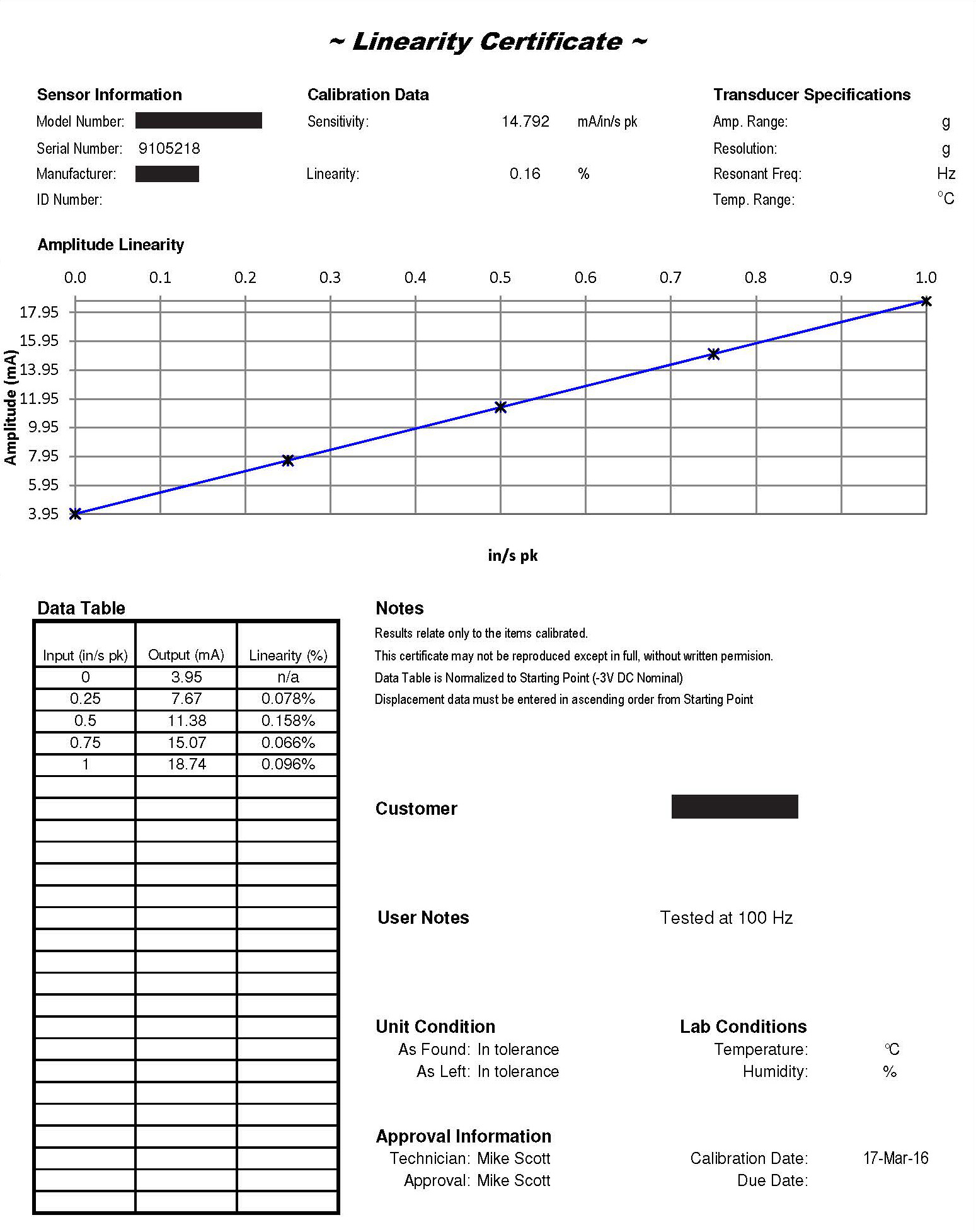
The good news is 4-20 vibration transmitters exhibit only a small amount of signal drift compared to pressure and temperature sensors. Most 4-20 mA vibration transmitters are a stiff construction with no moving parts. They use a ceramic piezoelectric sensing element housed between a center post and mass. The picocoulomb charge output of the piezoelectric element is converted to voltage by an internal charge amp. The voltage signal is then processed via RMS to DC converter, producing the 4-20 mA signal output proportional to vibration level. All of the electronics are typically inside a hermetically sealed, steel housing. The sensors drift more slowly than other process instrumentation. Typical drift results in the sensor losing sensitivity, thus as time passes it may no longer reach full scale output. Download the “example of signal drift” calibration certificate to see the calibration of a 4-20 mA sensor that comes up short of full scale range. Notice at the top of the certificate the sensitivity is only ~14.8 mA per inch per second when it should read 16 mA/ips.
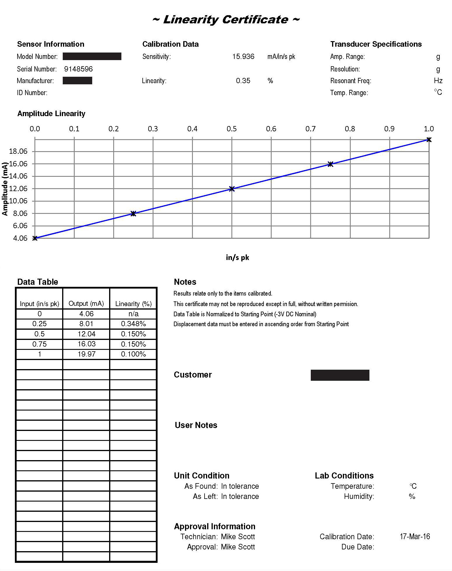
While there are no ISO or API standards that specifically discuss calibration of 4-20 mA vibration transmitters, manufacturers follow a similar procedure to that outlined in ISO 16063-21 for calibration of accelerometers. The back-to-back calibration method is used with the 4-20 mA vibration sensor mounted atop a shaker with known NIST traceable reference accelerometer. Output of the 4-20 mA sensor is compared to the output of the reference at various test points. This is typically done at speed of 6000 cycles per minute (100 Hz). Most manufacturers have shakers capable of driving the sensor under test to full scale range. A linearity test is conducted. The 4-20 mA sensor is tested first with no vibration and is eventually driven to full scale to confirm 20 mA output. Sometimes test points are taken at 25, 50 and 75% of full scale as well, depending upon the manufacturer’s specs. The 4-20 mA vibration transmitters “fail” calibration when full scale output does not come within a certain percentage of what is specified (% of span) or if non-linearity is greater than 1%.
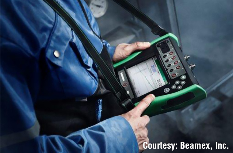 Equipment used for calibration of other process instrumentation
– such as the Beamex MC6 Field Calibrator – can also be used to test 4-20 mA vibration transmitters. The process is similar to
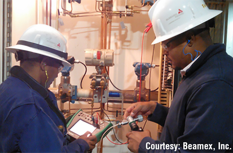
testing a pressure sensor with a hand pump. However instead of a hand pump the technician requires a shaker with reference transducer and display of known vibration input. Just like using a hand pump, the known vibration levels are manually documented
in the calibrator at the same time the 4-20 mA signal is measured and recorded. The documenting calibrator provides loop-power to the sensor under test and calculates % of span and non-linearity. It provides instant feedback to the technician regarding
whether or not the sensor passes or fails. Good practice is to enter the shaker’s calibration date, model number and serial number into the documenting calibrator’s database. Calibration records can be retrieved from the database during
an audit or when troubleshooting. The
ISA Interchange provides additional insight from Beamex’s Roy Tomalino and Katie Turner.
Equipment used for calibration of other process instrumentation
– such as the Beamex MC6 Field Calibrator – can also be used to test 4-20 mA vibration transmitters. The process is similar to
testing a pressure sensor with a hand pump. However instead of a hand pump the technician requires a shaker with reference transducer and display of known vibration input. Just like using a hand pump, the known vibration levels are manually documented
in the calibrator at the same time the 4-20 mA signal is measured and recorded. The documenting calibrator provides loop-power to the sensor under test and calculates % of span and non-linearity. It provides instant feedback to the technician regarding
whether or not the sensor passes or fails. Good practice is to enter the shaker’s calibration date, model number and serial number into the documenting calibrator’s database. Calibration records can be retrieved from the database during
an audit or when troubleshooting. The
ISA Interchange provides additional insight from Beamex’s Roy Tomalino and Katie Turner.
If the plant does not have a documenting calibrator, a test report can easily be made by hand. Many plants already use calibration forms where data is written down and filed away. The Modal Shop provides a manual method of creating a test report in its Calibration Workbook supplied with portable shakers that can either be rented or purchased.
Testing the 4-20 mA sensor while leaving it connected to the PLC or DCS and simulating actual usage conditions is good practice and provides the most confidence the sensor will operate correctly when called upon to shut things down in a potentially unsafe situation. The vibration transmitter is most sensitive to vibration at machine running speed and typically the control system is programmed with two alarm relays: alert and shutdown (or danger alarm). Hence it is good practice when calibrating or testing the sensor to generate vibration at the running speed of the machine onto which the instrument is mounted then drive the sensor to alarm and shutdown set points, confirming with the control room that the relays did indeed trigger. Displayed vibration inside the control room can also be compared vs. known vibration on the shaker’s display. This task is of course made easier if the vibration shaker used as a reference is portable and can be brought to the machinery where the sensor is located during an outage. IMI Sensors has written a white paper which further discusses 4-20 mA sensors, proper scaling and the frequencies at which machine failures occur.
Photos of the MC6 documenting calibrator courtesy of Beamex, Inc.